September 11th
 So, it was on to what I suppose ought to be home ground for me, although I haven't
done any electrical engineering for real for many years I do have some qualifications!
So, it was on to what I suppose ought to be home ground for me, although I haven't
done any electrical engineering for real for many years I do have some qualifications!
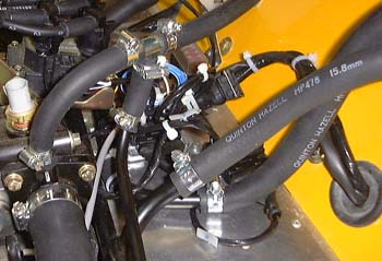
I spent a while tidying up the wiring in the engine compartment and then wired up the ECU. The magic box actually has a collection of connections that are hardwired to the box and a little connector with four wires for power and the tachometer connection. Although the tachometer is just above the ECU inside the car, the Westfield loom routes the connections to just under the inlet manifold. Rather than re-wire it inside the car I routed these additional connections out into the engine compartment (which is why you can see two cables coming through the big grommet in the picture on the right) and wired them in there. I connected the ECU power connection to one of the ignition circuits directly at the fuse box. I can't really remember which one it was, except that it was the one that seemed least loaded--I think it had the radio connection. (Yes, the Westfield loom includes a pre-wired connector for a radio, that most useful of accessories in car that will be so noisy you'll need earplugs! Having said that, I've a collection of old car radios, even including one with a built-in CD player, and there's a nice gap just in front of the gearlever...)
The only bit of this left is the mounting of the inlet air temperature sensor, which you may remember I am missing a nut for. The only problem with all this is that even though valiant attempts were made to keep it tidy it's still rather messy with wires and pipes all over the place, as you can see.
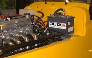 I mounted the battery tray, and the battery itself on the top of the footwell. This was
made a lot easier by my latest toy, a rivnut inserting device. This meant that the process of removing and installing
the battery will be a lot easier due to it not being required to grovel in the footwell to find the nut on the
end of the mounting bolt.
I mounted the battery tray, and the battery itself on the top of the footwell. This was
made a lot easier by my latest toy, a rivnut inserting device. This meant that the process of removing and installing
the battery will be a lot easier due to it not being required to grovel in the footwell to find the nut on the
end of the mounting bolt.
For some reason I ended up measuring the resistance presented to the battery and got a rather surprising 1.2 ohms. At first I assumed that this must be due to the fuel pump needing a lot of energy to get going. However, judicious juggling of fuses says that the low resistance is being presented by the off-side lighting circuits. Unless something like the alternator is also around this area and is confusing the measurements I will need to try and find out what is going on.
Perhaps I'll have to take everything to bits...
September 12th
Luckily, I didn't have to take too much to bits. After must head scratching and prodding with multimeter probes I finally realised that one of the fuseboxes (which were pre-wired to the chassis for me) had been connected up wrongly. This meant that one of the lighting circuits (which should of course be switched by the lights switch) was actually connected to the immobiliser circuit. The latter is non-switched which explains why is was sucking (non) current out of the battery all the time. The worrying thing is that two connectors had been transposed: one red one and one brown one. I am colour-blind and this is just the sort of mistake that I would make. I wonder if someone at Westfield doesn't know that they have this problem? (My family get fed up with me calling for colour-sensitive assistance at all sorts of odd occasions. Luckily all three of them have perfect colour vision.)
After that I connected up the side repeater lights and then (drum roll at this point) I connected the battery and turned on the hazard flashers. Everything went tick and flash, so success. I can even turn on the tail lights (no headlights yet). I did try turning on the ignition but turned it off quickly when the fuel pump started up, which is not too clever in the absence of any fuel at all.
Fitting the indicator repeaters was a bit fiddly as they require a rather precise hole cutting in the side of the car. The build manual includes a helpful "actual size" template, which is a bit if a pity as it is actually 50% bigger than actual size. I wonder how many people hack a big hole in the side of their car?
Finished off by drilling the last, hopefully, couple of holes in the boot box for the harness outer mountings. I keep thinking I've finished all the sawing, drilling and filing of GRP but it keeps coming back. I've got some holes to drill for the front indicators but I think that might be it.
September 13th
After spending a while talking to Chris Masters, I filled in the SVA form and posted it off. The problem is I will get a date in a while and that will give me a deadline, which will be a bit uncomfortable as I really don't want to rush anything.
I also phoned the parts department and asked them for the missing nut for holding on the air temperature sensor.
September 14th
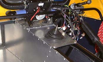 Fitted the first of the aluminium panels that cover the top of the transmission
tunnel. The first one is the one that goes around the gear lever. The manual implies that the hole for the gear
lever is already cut but it wasn't for me. I fitted the rubber gaiter first, riveting it from the bottom of the
panel.
Fitted the first of the aluminium panels that cover the top of the transmission
tunnel. The first one is the one that goes around the gear lever. The manual implies that the hole for the gear
lever is already cut but it wasn't for me. I fitted the rubber gaiter first, riveting it from the bottom of the
panel.
It seems a bit final this, actually closing it up!
September 15th
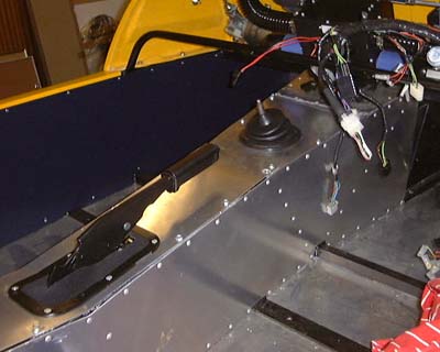 Finished
off filling in the transmission tunnel. The manual says that one of the plates is equipped with threaded inserts
in the chassis for bolting into, so that it can be removed for adjusting the handbrake. In my case at least this
is not true and my new toy, the rivnut too, came into its own again for putting the nuts into the chassis.
Finished
off filling in the transmission tunnel. The manual says that one of the plates is equipped with threaded inserts
in the chassis for bolting into, so that it can be removed for adjusting the handbrake. In my case at least this
is not true and my new toy, the rivnut too, came into its own again for putting the nuts into the chassis.
I also filled the gearbox with oil. Why is it that for a gearbox with an oil capacity of 1.2 litres Ford supply the (particular to this gearbox) in 1 litre bottles. And, why do Westfield just supply one bottle? (See the tips page for how to actually fill the gearbox!)
There was another sinking feeling at around this point. The carpet that covers the transmission tunnel has, according the manual, the gaiters for the handbrake and the gearlever sewn into it.
Not on mine it hasn't. I have a piece of carpet with nary a hole in sight and two nondescript looking pieces of blue vinyl.
Other people I have spoken to have said that their gaiters were sewn into the carpet for them, so I guess Westfield have screwed up again. This one will probably take ages to fix.
September 16th
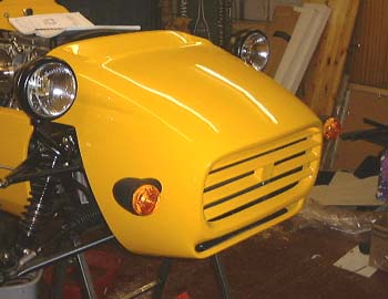 Did
the last job in module 5 today, which is the installation of the front indicators and the headlamps. Unfortunately,
the Westfield-supplied headlamps are really rather naff, perhaps I'll buy a pair of Cibies later on. Also, installing
the front sidelights is perhaps the hardest job I have done so far. In retrospect it would have been *much* easier
to install them before the radiator was installed in the nose and the nose was bolted to the car, as getting at
the bolts in the maze of chassis, wire and pipes is not funny.
Did
the last job in module 5 today, which is the installation of the front indicators and the headlamps. Unfortunately,
the Westfield-supplied headlamps are really rather naff, perhaps I'll buy a pair of Cibies later on. Also, installing
the front sidelights is perhaps the hardest job I have done so far. In retrospect it would have been *much* easier
to install them before the radiator was installed in the nose and the nose was bolted to the car, as getting at
the bolts in the maze of chassis, wire and pipes is not funny.
What's more I think they all, in common with most of the lights on this car, look rather dismal. It was also very hard to get the two lights to be positioned equally on the two sides of the car, mainly because the nose cone has so many 3-dimensional bends and curves that it is impossible to get a good reference from somewhere.
Also, the wires coming from the lights were too short, again. So far, I have had to lengthen wiring for:
- Fuel pump
- Rear light clusters
- Indicator side repeaters
- Cooling fan switch
- Front indicators
- Washer pump
This is getting beyond a joke, surely it wouldn't be hard to make these the correct, or at least too long, length?
in case you've got to this frame directly and can't get out, go here.