 I made a trip down to Dax in the morning to take back the tonneau that they
had got for me, and which turned out to be for a short wheelbase car. I also enquired about the carpet, as I was
surprised to find that I had not had something to cover the boot with. It turns out that I should have had something
but didn't get it. Sigh...
I made a trip down to Dax in the morning to take back the tonneau that they
had got for me, and which turned out to be for a short wheelbase car. I also enquired about the carpet, as I was
surprised to find that I had not had something to cover the boot with. It turns out that I should have had something
but didn't get it. Sigh...
In the afternoon it was back to Norwich again. I spent the first part of the journey checking the speedo calibration against the kilometre posts on the road. Just after I'd got it exactly right, or so I thought, the speedo stopped moving entirely. BUGGER!
 Oh well, this time I'll fix it properly. I turned the car round and stopped
for some petrol. I phoned the test centre from the car park there and rebooked a test for next Tuesday morning.
(The 21st, I think.) When I got home I phoned up Merlin
Motorsport and ordered a proximity sensor for the speedo. I arranged for it to be delivered to the office tomorrow
morning, supposedly. I think this sensor should be like the one that Westfield use. In that case it works by sensing
the bolts in the Lobro joint going past. I never had the slightest bit of trouble with it so perhaps that's the
way to go. The obvious problem is that on the IRS car there's some useful bits of chassis around the diff for mounting
the sensor on. In the de Dion car this isn't the case as there's a stonking great de Dion tube flailing about.
Still, it must be possible to do something, he said hopefully.
Oh well, this time I'll fix it properly. I turned the car round and stopped
for some petrol. I phoned the test centre from the car park there and rebooked a test for next Tuesday morning.
(The 21st, I think.) When I got home I phoned up Merlin
Motorsport and ordered a proximity sensor for the speedo. I arranged for it to be delivered to the office tomorrow
morning, supposedly. I think this sensor should be like the one that Westfield use. In that case it works by sensing
the bolts in the Lobro joint going past. I never had the slightest bit of trouble with it so perhaps that's the
way to go. The obvious problem is that on the IRS car there's some useful bits of chassis around the diff for mounting
the sensor on. In the de Dion car this isn't the case as there's a stonking great de Dion tube flailing about.
Still, it must be possible to do something, he said hopefully.
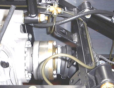
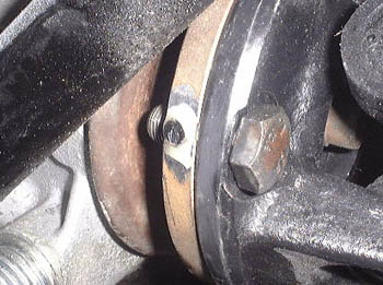
The photo here shows the speed sensor mounting bracket on the back of the Westfield. It's that bracket above and to the right of the Lobro joint.
On the way back I got a little concerned about a vibration in the car at high speeds. However, I'm not even sure it's there and might have been caused by the wind hitting my crash helmet. (I was wearing one because in the absence of side-screens they make driving a lot easier.) However, I had also noticed something while I was running the car in the garage checking the speedo settings a while ago. Perhaps the rear wheels just need balancing rather better than they are at the moment.
Oh well, at least I've got something to do in the garage again!
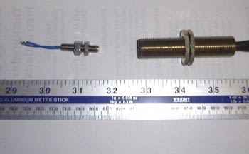 So, it was back to the garage yet again. The proximity sensor arrived, as promised,
this morning. It's a much bigger beast than the reed switch sensor, as you can see in this comparative photo.
So, it was back to the garage yet again. The proximity sensor arrived, as promised,
this morning. It's a much bigger beast than the reed switch sensor, as you can see in this comparative photo.
That photo was actually taken after I took the reed switch out, as I started by taking the tunnel out...
 ...yet again. At least I'm getting quicker at doing it now. (If I had the one-piece tunnel
of the SWB cars this would be a nightmare.) The problem is that continually re-glueing things isn't clever really.
...yet again. At least I'm getting quicker at doing it now. (If I had the one-piece tunnel
of the SWB cars this would be a nightmare.) The problem is that continually re-glueing things isn't clever really.
Having done this is was obvious that, as I suspected, the other magnet had finally disappears. In fact, there are a couple of odd issues down here. First of all, the rear of the gearbox is leaking oil slightly. I wonder if this is anything to do with the fact that there isn't a speedo sensor plugged in there? That doesn't seem likely. I shall have to phone up Dave Ellis and see what he thinks about it.
Also, something I'd noticed before and discounted really, is that the bits of araldite left over on the propshaft are rather soft, which seems very odd. I did wonder if these two things could be related in any way.
Anyway, I cut off this wires to the reed switch (hence the short wires in the photo above) and soldered some much longer cables on to the left over bits.
On looking at the reed switch it was obvious that it had contacted the magnets at some point, as there was quite a lot of wear there. However, if the magnet had stayed attached perhaps it would have eventually settled to the ideal spacing...
 I had decided to adopt a bit of a belt and braces approach and the first thing
to do was to re-position the magnets and try and attach them to the flange on the front of the diff. I went to
a lot of trouble to clean everything up before Aralditing things in place. It'll be interesting to at least look
at these magnets in a while.
I had decided to adopt a bit of a belt and braces approach and the first thing
to do was to re-position the magnets and try and attach them to the flange on the front of the diff. I went to
a lot of trouble to clean everything up before Aralditing things in place. It'll be interesting to at least look
at these magnets in a while.
Again, I stuck four magnets on here, hoping that if I have to use them then the larger radius of the diff flange will help the sensing. I bet that I don't use them and they end up never moving a millimetre...!
Having got the Araldite setting, I could start looking at the proximity sensor mounting. It's obvious that I'm going to have to do a bit of metal work to support this.
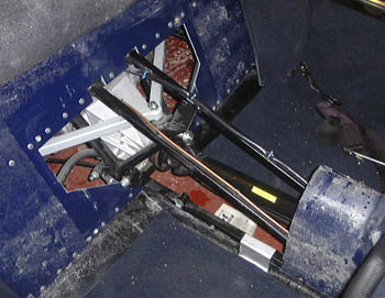
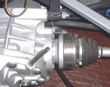 This photo shows the Lobro joint on the driveshaft, much like the Westfield
one above, but without the bits of chassis that the IRS car has here.
This photo shows the Lobro joint on the driveshaft, much like the Westfield
one above, but without the bits of chassis that the IRS car has here.
I think the thing to do will to fabricate a steel bracket that will bolt to the diff mounting bolts, which you can see have enough thread on them for a bit more work there! I'll have to arrange for this bracket to permit the sensor to be mounted at the suitable angle for it to "point" at the Lobro joint bolts. It'll be a bit tricky but shouldn't be impossible. One problem is to make sure that the sensor isn't in danger of being whacked by the suspension. For example, the diagonal bar in this is the A-frame that locates the de Dion bar laterally. Obviously, this moves up and down fairly violently and would make mincemeat of the proximity sensor.
However, all that's going to take some time, so it'll have to be left until tomorrow.
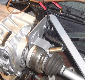
 Having thought about how to make a bracket to support the proximity sensor for
quite a while I decided how to go about it. What I made just hangs on one of the diff support bolts, the one that
can be seen in the photo above. and is stabilised by a small rivnut inserted into the small bit of chassis just
above. After a lot of measuring and trignometry, again, I managed to get the sensor mounted at 45° to the Lobro
joint bolts. This matches what the Westfield was like, more or less.
Having thought about how to make a bracket to support the proximity sensor for
quite a while I decided how to go about it. What I made just hangs on one of the diff support bolts, the one that
can be seen in the photo above. and is stabilised by a small rivnut inserted into the small bit of chassis just
above. After a lot of measuring and trignometry, again, I managed to get the sensor mounted at 45° to the Lobro
joint bolts. This matches what the Westfield was like, more or less.
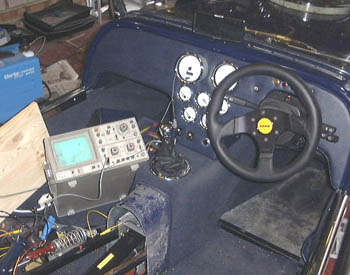
With the bracket made I could lash it up to see if it worked. In fact, I even dug out the 'scope, as you can see!
At first, it didn't work at all. However, after moving it closer to the lobro bolts it got better. Intriguingly, it has the opposite sort of behaviour to the reed switch sensor in that it's happiest at high speeds. This isn't such a bad thing in that the SVA manual says that the minimum testing speed of the speedo is 35mph. (Given the preponderance of 30mph speed limits that seems a little odd?) At low speed the amplitude of the sensor signal, as seen on the scope, drops a lot. All the same, but lowering the gap I managed to get it working pretty well. At least this time there's no magnets to be knocked off by the sensor moving a bit too close when the drive line moves about a bit.
Certainly, once the speed gets above 20mph the display seems very stable. Let's hope it stays together on the ride to Norwich.
 With the testing done I could finish it off properly. So, I took the bracket
off again and Hammerited it to make it at least a bit more resiliant to the elements. I also sorted the wiring
out so that it was actually using the same wiring as the previous sensor used, albeit wired differently to the
back of the speedo.
With the testing done I could finish it off properly. So, I took the bracket
off again and Hammerited it to make it at least a bit more resiliant to the elements. I also sorted the wiring
out so that it was actually using the same wiring as the previous sensor used, albeit wired differently to the
back of the speedo.
Although it doesn't look like it in the photo, the A-frame doesn't hit the sensor, I hope. I need to make absolutely sure that the boot box doesn't get in the way, but I'm pretty sure it doesn't.
With that, it was rather too late in the day to test it properly again, as driving at 11pm in the garage isn't going to endear me to the neighbours. I'll sort it tomorrow morning.
After all the faffing about, I put the car back together. At least with the speed sensor at the back of the car now I can at least get at it without taking the tunnel apart.
I'm still a bit concerned about the amount of oil there is around the rear of the gearbox. I'll have to keep and eye on it and see if it gets any worse.
in case you've got to this frame directly and can't get out, go here.