 Well, there’s a bit more progress to tell you about. First of, the panelling is almost completed. The first part of this was putting the seat backs in place, as seen in the photo on the right. These are actually held in with rivnuts, as I reckon being able to remove them will be quite useful, for example for getting at the exhaust.
One concern about the car’s design, to be honest, is the proximity of the poor old driver’s back to the exhaust headers. These are, of course, rather hot and it’d be nice to keep my back coolish. Being an outlandishly large chap (even if I could rid myself of all the flab) my back is rather closer to these headers than I’d like as there’s no room to fit in a nice large insulating wodge of seat foam. As a consequence I’ll probably make sure to fit some insulating gubbins to the engine side bit of the seat back before finishing the car.
 It’s odd, putting these bits in, as the car suddenly looks much more complete, I think because the driving bit is now more separate from the engine area.
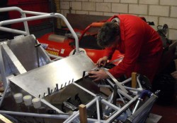
For ages I’ve been fretting about how to do the panelling at the front of the car, and in particular over the pedals. However, I had a brainwave in that I thought I’d fool someone else to do it for me. So, here’s a photo of Adrian slaving over a hot panel. Even better that that one, he worked out how to do the panel over the footwell. 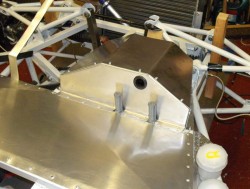 Admittedly, he shoved off before actually making this bit, but he’s forgiven. Later on I actually made the top panel which is in the next photo on the right.
There’s a final bit of this to do, the panel at the front of the this new “tent”. However, I’ve actually made that, I just haven’t rivetted it in. Again, you can see that the top panel is held in here with rivnuts, as getting access to the pedals and master cylinders is clearly really important.
I’m just about ready to start wiring the car (at which point 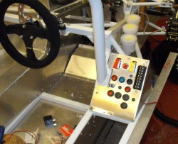 I’ll be able to start it!). First step here, apart from slaving over a hot diagram that is, is to make the switch panel. After seeing what Jeremy did on the prototype J15 I’ve put the panel in the same sort of place, as in the photo. And yes, you can get the bodywork on.
Of course, there aren’t actually any wires attached yet, but I’ll start that real soon now. I’ve actually decided to take a slightly different approach with the wiring in that this panel is going to become Grand Central with all the bits of the loom coming in and out here. This means that some of the wires will be slightly longer than necessary. However, it’ll mean that each bit of the loom, such as the part that goes from here to the logger, is separate which should make things a bit easier to make, and debug when necessary.
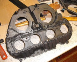 One thing I’ve been fretting about for ages in how the engine induction is going to work. Eventually, I decided to base it all, at least for now, on the standard Honda airbox, although that will have to be turned around so that it sticks back. In order to do this I had to cut and shut the airbox, as it’s designed to go the other way around and hence, for example, the mountings for the throttle bodies are the wrong way around. With some investigation I found that the ‘box is polypropylene which, being a thermoplastic, can be “welded”. You can even buy plastic “welders” to do this sort of thing. Some of these are essentially hot air guns but the one
  I got was rather cheaper and is essentially a soldering iron.
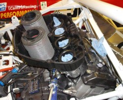
The next photo is the underside of the modified airbox, you can see the “welding” rather easily. When mounted on the car, it looks like the next photo. The air filters in this photo are actually upside-down as on the bike the air inlet comes into the bottom of the airbox. I haven’t actually worked out yet how to do this on the J15. I had wondered about ducting air around to the bottom of the ‘box. The other possibility it to butcher the top panel of the airbox as well, which can be seen in the next photo, and arrange air to flow into the filters from the top. This is the reason why they’re upside down in the photo, I might well run them in this position. Certainly other CBR1000s run with the filters 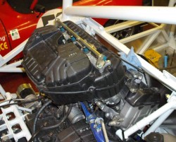 upside-down like this and they seem to run fine.
Mind you, it’d be nice to retain the top of the engine like this as this is where the ECU mounts normally, and the engine loom has the cabling set up to work from this position. However, I can always change the wiring, as I did on the Fury. It’s quite a lot of work though.

another option with the airbox is to swap around the whole injector rail and airbox assembly , leaving the wiring as is so no 1 coil / injector wiring /plumbing remains there whatever position the rail is in – this would have saved the airbox butchery ??
No, that wouldn’t work, if I understand you. If the airbox is bolted on in the standard position it’d sit in the same position as the chassis and roll-hoop. (In the bike it pokes up and forward, snugly inside the chassis frame.) So, it needs to be turned around and the butchery is necessary because the throttle body mounting flange is handed. Yes, the secondary injectors are now above the “wrong” throttle bodies but that easily fixed by swapping the connector around, which would be no issue with the ECU in the standard position. Mind you, the whole lot is above the engine cover so that needs sorting anyway as the scrutes will object to it in this position.
The other issue is, of course, that the fuel rail connections need changing but that’s no big deal.
Tim
what i meant ( but probably explained badly ) was to effectively undo the whole throttle body assembly , lift up and rotate 180 degrees complete with airbox and then reattach wiring etc with no 4 now being no1 etc – i remember it working really well on the r1 but cant remember if same applied to cbr –
Oh I see. Sorry, was being stupid.
I must admit that I hadn’t thought about doing this. However, I’m fairly sure that something would hit the head if the throttle bodies were turned around. The most obvious bit would be the fast idle adjustment gubbins which is plumbed into the coolant circuit (although you could presumably get by without that). I also suspect the fuel rail itself might be in the way.
Nice idea though. However, I’m not about to un-butcher the airbox… 🙂
Tim