 Things have been a bit hectic recently and I haven't kept this page as up to date as I
usually manage to. Hence, this entry is a bit of a catch-all.
Things have been a bit hectic recently and I haven't kept this page as up to date as I
usually manage to. Hence, this entry is a bit of a catch-all.
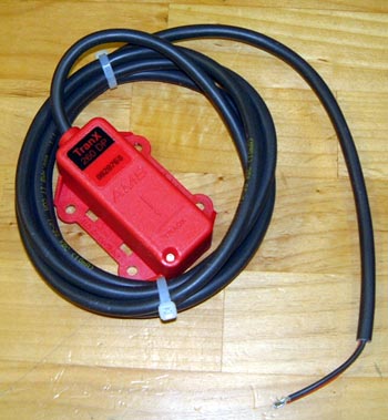
First of all, the transponder that I ordered arrived. I must admit to being a bit miffed that the transponder that is required by the race series operated by a low-cost motor sport club costs just about £200 for something that should cost about £30. I mean, all it is is a little RF oscillator. Admittedly carefully tweaked but that's no big deal. Oh well, at least it arrived promptly.
The next thing to think about was the propshaft. There's now a pretty much standard supplier of these for bike engined cars which is a fairly local company called Bailey Morris. I phoned them and they faxed me a measurement sheet to fill in which contains all the various measurements, the type of centre joint and details of the flanges required at each end. The propshaft is in two pieces with a centre bearing (I believe from a Ford Transit) in the middle. I measured everything up, several times and filled in the form. One problem was the size of the input flange as it didn't seem to match any of Bailey Morris's standard sizes. However, after talking to the chap who supplied my adapter and the helpful people at Bailey Morris I think I sorted it. However, when it arrives anything could be the case!
I actually specified the length of the rear part of the shaft as being 2mm shorter than it actually measures. The reason is that I need to get a reversing solution as, rather bizarrely, this is required for the race series. Originally the BEC people used mechanical reversing boxes but these have proved to be rather troublesome. The now standard approach is to use another starter motor and some gearing so as to make and electric reverse. They do tend to make the car sound as is it's a milk float but they seem to be effective. I decided to buy one from Gordon Griffin who is a fellow RGB racer. (Except he actually goes to the races!) Gordon makes them as a spare time activity. He makes them in two forms: one that fits by the diff and one that fits by the gearbox. The better one for me seems to be the diff mounted one and that's what I've gone for. The 2mm is accounted for by the ring gear needed being, according to Gordon, 2mm thick.
With luck I'll be able to get to Snetterton at the weekend and I can pick up the reversing gubbins from Gordon there.
So, it was also time to get on with the bodywork. From past experience I know this is always the most difficult bit. At least this means I no longer get dispirited when it just doesn't seem to fit, which always seems to be the case. In fact, experience is that when you offer up the bodywork for the first time it doesn't fit by so much that you can convince yourself that there's something really wrong with everything.
 Having fitted the boot floor a while ago I started trying to fit the rear tub. The normal
approach to building a Fury is to bond the rear tub to the boot floor. However, this makes a pretty immovable object
and a standard racing tweak seems to be to make it removable. Luckily a short while ago Gordon (as above) posted
some pretty explicit instructions on how to do this on the BEC mailing list which I intend following. All the same the first thing to do is to get the rear
tub to fit and, after taking off the steering column which is in the way it became immediately apparent that this
was going to be even harder than for previous cars. If only because the bits of GRP are rather large and difficult
to manoeuvre.
Having fitted the boot floor a while ago I started trying to fit the rear tub. The normal
approach to building a Fury is to bond the rear tub to the boot floor. However, this makes a pretty immovable object
and a standard racing tweak seems to be to make it removable. Luckily a short while ago Gordon (as above) posted
some pretty explicit instructions on how to do this on the BEC mailing list which I intend following. All the same the first thing to do is to get the rear
tub to fit and, after taking off the steering column which is in the way it became immediately apparent that this
was going to be even harder than for previous cars. If only because the bits of GRP are rather large and difficult
to manoeuvre.
One of the parts of Gordon's instructions relate to strengthening the boor floor with a rear "side" as it does not get firmed up by being bonded to the rear tub. This was achieved by riveting a specially cut piece of aluminium across the rear of the boot area.
 The side pods for the Fury essentially side on small bits of aluminium "floor"
that stick out beyond the chassis. There are a couple of extension pieces that extend this floor further forward
and the main tub floor and these were fitted first.
The side pods for the Fury essentially side on small bits of aluminium "floor"
that stick out beyond the chassis. There are a couple of extension pieces that extend this floor further forward
and the main tub floor and these were fitted first.
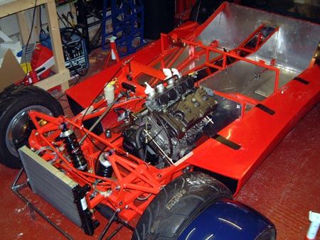
 Then, Tom (luckily it's the Universityr vacation time) and I spent a while putting
the rear tub on and off trimming bits off the boot floor so as to fit properly. Once we were getting somewhere
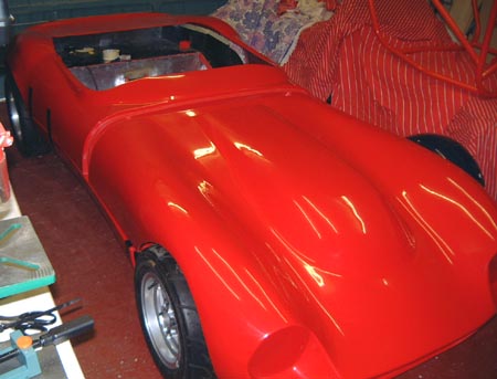
we tried hanging all the bodywork panels on the car. This really only served to emphasise two things: we were way
away from achieving a decent fit and it really is very red!
Then, Tom (luckily it's the Universityr vacation time) and I spent a while putting
the rear tub on and off trimming bits off the boot floor so as to fit properly. Once we were getting somewhere
we tried hanging all the bodywork panels on the car. This really only served to emphasise two things: we were way
away from achieving a decent fit and it really is very red!
 One obvious thing was that we didn't have the sidepods in anything like the
right place. First of all they are clearly too short (but see above about it never fitting right!) and the side
impact beams are rather getting in the way of fitting the side pods snug to the side of the car.
One obvious thing was that we didn't have the sidepods in anything like the
right place. First of all they are clearly too short (but see above about it never fitting right!) and the side
impact beams are rather getting in the way of fitting the side pods snug to the side of the car.
So, we took it all off again and started hacking the sidepods until they fitted properly. We've only done one so far but it's much better than it was. So, once this is done we'll try the whole body again!
 Bailey Morris phoned today to say that the propshaft was ready. So, I'll go
up there tomorrow and pick it up.
Bailey Morris phoned today to say that the propshaft was ready. So, I'll go
up there tomorrow and pick it up.
In the evening, though, I got into the garage and got on with the bodywork. I made up some brackets to attach the right hand sidepod to the side of the chassis. This whole business is made much complicated by the side impact towers, but I'll just have to put up with that. I realised as I was doing this that the sidepod is going to make getting at the bottom of the bolts that hold the roll cage on just about impossible. There seems no solution other than cutting some access holes in the top of the sidepod.
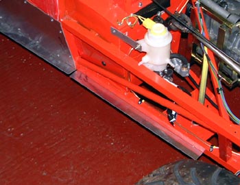
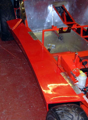
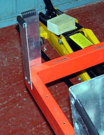
 The rear of the sidepod is actually some way away from the side of the car, so it has to
be secured with a rather large aluminium flange, as in the photo here.
The rear of the sidepod is actually some way away from the side of the car, so it has to
be secured with a rather large aluminium flange, as in the photo here.
The worry about all this is deciding that the body is not in the right place and having to move the sidepods. I was thinking about some sort of moveable mounting but that would just seem to add unnecessary weight to the car.
 After that I started doing the same thing to the left hand side of the car.
However, I haven't made any brackets for that side yet. First of all because I ran out of time and secondly because
the left hand sidepod has the exhaust system in side it. I haven't got this yet and it's bound to get in the way
even more. In fact, I keep wondering whether it's going to bash in to the side impact structures.
After that I started doing the same thing to the left hand side of the car.
However, I haven't made any brackets for that side yet. First of all because I ran out of time and secondly because
the left hand sidepod has the exhaust system in side it. I haven't got this yet and it's bound to get in the way
even more. In fact, I keep wondering whether it's going to bash in to the side impact structures.
 The plan was that I was going to spend a lot of this weekend working on the
car and make a lot of progress. Unfortunately, it seems that I did the former and not the latter, mainly because
fitting the bodywork is taking a lot of time, which I guess I always knew it would.
The plan was that I was going to spend a lot of this weekend working on the
car and make a lot of progress. Unfortunately, it seems that I did the former and not the latter, mainly because
fitting the bodywork is taking a lot of time, which I guess I always knew it would.
The weekend started last Friday with a trip up to Bailey Morris to pick up the propshaft. At first sight it looks like an excellent piece of work. It will need a bit of work to get it to fit with the minimum of joint angles, but probably fine.
However, in advance of that I wanted to get the car's bodywork more finished, as from past experience I know that's pretty much the biggest job that's left.
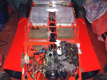
 One thing I do now know about the bodywork, as a result of trying it in position several times, is
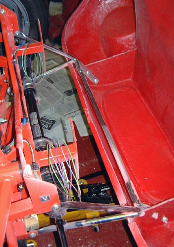
where the scuttle part of the tub moulding is going to go. As a consequence, I wanted to move the loom connection
slightly. So, I did this and also added the other part of the wiring loom, that that connects to the engine compartment.
This results in this bunch of four connectors sticking up under the dash. The rest of the wiring is, though, just
sitting in a pile on top of the engine.
One thing I do now know about the bodywork, as a result of trying it in position several times, is
where the scuttle part of the tub moulding is going to go. As a consequence, I wanted to move the loom connection
slightly. So, I did this and also added the other part of the wiring loom, that that connects to the engine compartment.
This results in this bunch of four connectors sticking up under the dash. The rest of the wiring is, though, just
sitting in a pile on top of the engine.
The reason there are so many connections here is that I'm trying to get all of the electrics accessible on the dash. So, for example, the fuse box will be there rather than hidden on the scuttle.
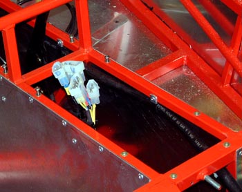
 After that, it was back to the rear tub. Again as a result of making it removeable,
I cut away much of the surplus moulding inside the tub that returns from the edge of the body to the chassis. You
can just about see the edge of where I cut it back to in this photo.
After that, it was back to the rear tub. Again as a result of making it removeable,
I cut away much of the surplus moulding inside the tub that returns from the edge of the body to the chassis. You
can just about see the edge of where I cut it back to in this photo.
What's more, the GRP removed by doing this weighed nearly one kilogram! I've lifted the tub on an off loads of time now, and you can really tell the difference.
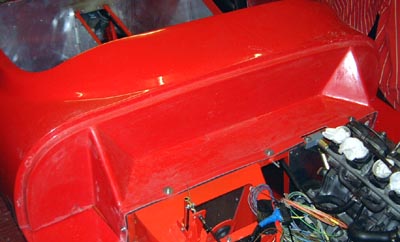
 However, after more experimentation with the bonnet (it's amazing what you can
hold on with gaffa tape) several things became clear: the radiator was in the way of the bonnet, the bonnet hinge
was also in the way somehow, the body was too low in that it was bashing on the wheels and, most important, the
bonnet wouldn't go far enough back to meet up with the sidepods properly.
However, after more experimentation with the bonnet (it's amazing what you can
hold on with gaffa tape) several things became clear: the radiator was in the way of the bonnet, the bonnet hinge
was also in the way somehow, the body was too low in that it was bashing on the wheels and, most important, the
bonnet wouldn't go far enough back to meet up with the sidepods properly.
So, I decided to move the sidepods forward by 1cm. After much faffing about that was done and it seemed much better in that things could be just about made to fit right. (Although still with the aid of lots of gaffa tape!)
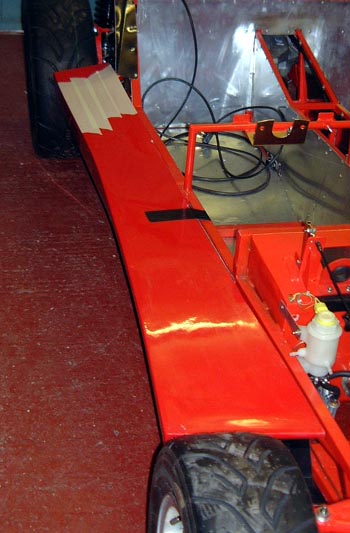
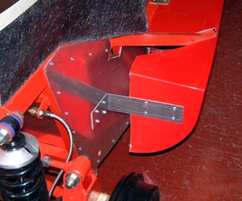
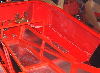
 At the back of the car,
I just couldn't the rear tub to sit on the top of the boot floor sides properly. After looking around at what a
lot of other people have done I eventually decided to cut the rear half of the boot floor away (on account of the
fact that luggage space is not exactly what I'm aiming for). This will also allow better access to the fuel tank/suspension
area. So, I made a new "wall" for the rear of the truncated boot which now looks like this photo here.
At the back of the car,
I just couldn't the rear tub to sit on the top of the boot floor sides properly. After looking around at what a
lot of other people have done I eventually decided to cut the rear half of the boot floor away (on account of the
fact that luggage space is not exactly what I'm aiming for). This will also allow better access to the fuel tank/suspension
area. So, I made a new "wall" for the rear of the truncated boot which now looks like this photo here.
In fact, I seem to have inadvertantly made one of those useful shelves upon which tools will now accumulate in an uncontrolled fashion. (And, you're right, I'll have to cut some holes in this bit for the harnesses.)
 As I expected, doing this had the side effect of making the rear
of the rear tub moulding rather obviously unsupported. I could have fixed this with the struts at the bottom, but
that would probably degrade the removeability. So, I made a couple of support pillars which are rivetted at the
very rear of the chassis.
As I expected, doing this had the side effect of making the rear
of the rear tub moulding rather obviously unsupported. I could have fixed this with the struts at the bottom, but
that would probably degrade the removeability. So, I made a couple of support pillars which are rivetted at the
very rear of the chassis.
That all seems to work pretty effectively. The one remaining problem is that GRP sides of the boot floor. After much fiddling about these still don't really support the tub that well. I even resorted to cutting one of the sides fairly drastically and re-bonding it back together in a better position.
I'm trying to decide whether it's best to just abandon the GRP and make some aluminium panels of the right shape.
 As part of making everything fit, I worked out a bit where the exhaust was going to be
in the left hand sidepod and then fixed that to the car. In this case I used rivnuts for the connections to the
chassis so that I can take the sidepad off when I need to.
As part of making everything fit, I worked out a bit where the exhaust was going to be
in the left hand sidepod and then fixed that to the car. In this case I used rivnuts for the connections to the
chassis so that I can take the sidepad off when I need to.
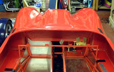
 Finally, it was time to attach part of the rear tub to the car. This was done
with some rivnuts and M5 bolts, as well as some small aluminium brackets that attach to the sidepods (and don't
appear in the photo!).
Finally, it was time to attach part of the rear tub to the car. This was done
with some rivnuts and M5 bolts, as well as some small aluminium brackets that attach to the sidepods (and don't
appear in the photo!).
The next step will actually be to cut the vertical scuttle section from the rest of the rear tub. This is going to make it even lighter and floppier! However, I need a while to pluck up the courage to do that!
One problem that's occurred to me about the removeable bodywork is that there's nowhere for electrical isolator to me mounted. I shall have to see if putting that on the dash too, suitably marked, is OK for the scrutineers. I'm going to the RGB race at Snetterton tomorrow, so with luck I'll be able to look at a few other cars to see how they do it all!
 I spent most of today at the 750 MC race meeting at Snetterton. And, I've got
the sunburn and water-logging to prove it. :-)
I spent most of today at the 750 MC race meeting at Snetterton. And, I've got
the sunburn and water-logging to prove it. :-)
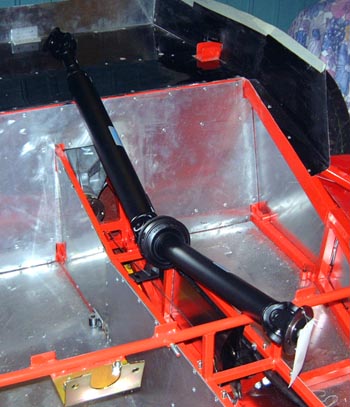
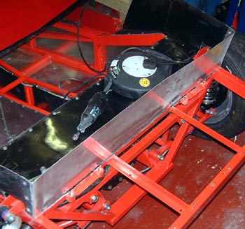
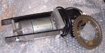
While there I picked up the reverse mechanism from Gordon Griffin which is shown in the photo here. It's essentially two bits: a ring gear that bolts onto the input shaft of the differential and a device built around a bike starter motor which has to be positioned near the ring gear. This has a cable that has to be pulled to engage the gears and the motor can then be powered by a normal starter relay.
The only problem is that as Gordon described it to me, the motor is supposed to be positioned under the propshaft. However, in my case that's going to foul the handbrake cables. However, I think there's room to mount it above, although it might need a bit of a power bulge in the tunnel top to clear the tail of the motor. (And there's a mounting lug there that might be best ground off.
After I got home I spent a bit of a while bolting the scuttle part of the tub down a bit more firmly, ready to slice it in two...
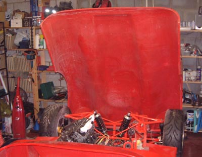 Before I chop off the front of the tub, I decided it would be a good idea to
fit the bonnet, before I make the thing it mates against nothing like as substantial as it is at the moment! So,
I bolted the hinge frame back onto the car, hoping that this time it was going to fit a bit better, and then spent
an age getting the bonnet into what seems like a sensible position. It does seem to me, though, that to get down
to the minimum ride height I'm going to have to relieve the wheel arches a bit to avoid the tyres contacting them.
Before I chop off the front of the tub, I decided it would be a good idea to
fit the bonnet, before I make the thing it mates against nothing like as substantial as it is at the moment! So,
I bolted the hinge frame back onto the car, hoping that this time it was going to fit a bit better, and then spent
an age getting the bonnet into what seems like a sensible position. It does seem to me, though, that to get down
to the minimum ride height I'm going to have to relieve the wheel arches a bit to avoid the tyres contacting them.
 After that I drilled through the moving bits of the hinge frame into the bonnet
and bolted the bonnet to the hinge. I then discovered that I couldn't open the bonnet as some of the moulding bashed
into the hinge then the bonnet was moved. After a serious dremeling I got it so that I could open it reasonably
easily.
After that I drilled through the moving bits of the hinge frame into the bonnet
and bolted the bonnet to the hinge. I then discovered that I couldn't open the bonnet as some of the moulding bashed
into the hinge then the bonnet was moved. After a serious dremeling I got it so that I could open it reasonably
easily.
I was worried that it was going to be mega-floppy, but it isn't too bad.
The big problem now is that I can't get my jack out from under the car with the bonnet in place! For some time I've been thinking that I'd have to buy a quicklift jack but it's looking more urgent by the second at the moment.
The car's going to have to stay on stands for a while now....