 With the pedal box back together structurally I checked out that it seemed to
hold together by getting in the car and shoving as hard as I could on the end panel. I actually managed to cramp
up the muscles in my calves doing this without any sign of problems in the car so I suppose that should be OK.
That's more than can be said for me though. It took me a while to climb out again.
With the pedal box back together structurally I checked out that it seemed to
hold together by getting in the car and shoving as hard as I could on the end panel. I actually managed to cramp
up the muscles in my calves doing this without any sign of problems in the car so I suppose that should be OK.
That's more than can be said for me though. It took me a while to climb out again.
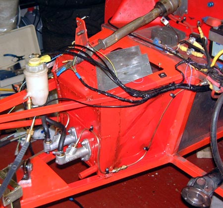
With that done I put the pedal box and master cylinders back in, although they remain to be reattached together. One thing I will do while the sidepod is off is to make the brake bias adjuster work a bit better. I bought a slightly longer cable from Rally Design which should make this a bit easier but I'll probably need to modify the place that the cable enters the pedal box on account of the pedals being a bit further forward now.
Unfortunately, I had to make the brake pipe take a slightly circuitous route so as to cleare the engine mounting cradle. However, as I've since got the engine is there is a rather better route to take but I think I'll leave it alone as I don't want to mess around with the pipe any more that I absolutely have to.
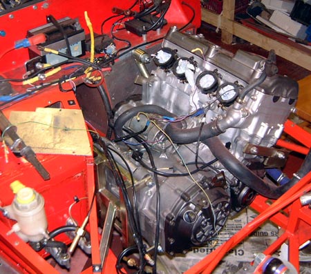 With that done I could get back to putting the engine in. It really is absurdly
easy to manoeuvre a thing like a bike engine into position in the chassis. Compared to this it was ridiculously
hard to get the Rush engine in and out, although I suppose being a socking great V8 that's not surprising.
With that done I could get back to putting the engine in. It really is absurdly
easy to manoeuvre a thing like a bike engine into position in the chassis. Compared to this it was ridiculously
hard to get the Rush engine in and out, although I suppose being a socking great V8 that's not surprising.
With the engine back here I moved onto sorting out the engine wiring. Unlike the previous one this engine has got the small loom that connects to things like the oil pressure switch and it's also got the proper 'blade speedo sensor. So, I wired this lot into another connector so as to neaten things up. I will, though, possibly have to change one bit of this when I sort out the pressure gauge fittings. I've bought a bewilderingly complicated array of pipe fittings and hose from Think which will enable me, I think, to make some sort of attachment for the pressure gauge and switch that isn't going to fall apart this time. At least, I hope so. As usual, I'm left wondering if the world really does need this array of bizarre pipe fittings.
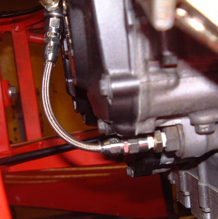 I fixed in the first attempt at sorting the oil pressure fittings. However,
it's really a bit over the top and I think I'm going to rationalise it a bit. The original approach was really
much neater; although it did have the slight flaw of failing and causing an engine blow-up.
I fixed in the first attempt at sorting the oil pressure fittings. However,
it's really a bit over the top and I think I'm going to rationalise it a bit. The original approach was really
much neater; although it did have the slight flaw of failing and causing an engine blow-up.
With that half done I connected up some of the water hoses so the engine is now getting closer to being able to be run. I guess at the moment I'm just assuming that the engine will be fine but I really ought to check it soon.
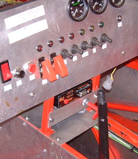 I've been thinking a lot about using the DL1 as the main source of information for a gear
indicator and it really does seem like a sensible notion. However, it would be more convenient if the DL1 was a
bit more easily accessible in the car. So, I did something I've been meaning to do for a while and made a different
shelf for it, in the centre of the car where the fire extinguisher release is.
I've been thinking a lot about using the DL1 as the main source of information for a gear
indicator and it really does seem like a sensible notion. However, it would be more convenient if the DL1 was a
bit more easily accessible in the car. So, I did something I've been meaning to do for a while and made a different
shelf for it, in the centre of the car where the fire extinguisher release is.
To be completely honest, I haven't actually worked out how to attach the DL1 to its little shelf yet. Or, I didn't when I took the photo. I have now got an idea that I shall implement when I've got a moment. As can be seen in the photo, I've moved the extinguisher release to the front of the DL1 shelf, in much the same position it was before really, although now a bit closer to me. As I've now removed the gearchange from this position I don't have to worry about it bashing into that.
One issue with this shelf is that it isn't as protected from the elements as the sandwich box on the floor was. Perhaps some sort of plastic rain hat would do the job as well here.
I did also start sorting out the wiring a little, but didn't get too far.
I've also been thinking about what sort of device to connect to mount on the dash to display the current gear. I was originally thinking that I'd make some sort of little bunch of electronics with a small LCD display. However, Anthea pointed out that something like an old PDA (say a Palm or an IPaq) would do the job too and would probably have a better display. Hmmm, interesting thought. The only problem is I've never really found out how to program such things. I do use a Palm Pilot all the time though...
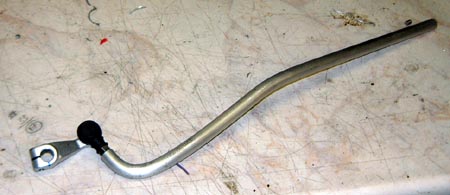 One of the main reasons for starting this mammoth rebuilt was to make a paddle
gearchange, and I finally got around to doing some of this. First of all, I managed to make a rod to actuate the
change itself. I had been hoping to use the pukka Honda actuator arm as that must be up to the job and I made this
rather bizarre rid to connect directly to it. I actually bought an M6 left hand tap to tap the end of this rod
so that it screws directly onto the actuating lever.
One of the main reasons for starting this mammoth rebuilt was to make a paddle
gearchange, and I finally got around to doing some of this. First of all, I managed to make a rod to actuate the
change itself. I had been hoping to use the pukka Honda actuator arm as that must be up to the job and I made this
rather bizarre rid to connect directly to it. I actually bought an M6 left hand tap to tap the end of this rod
so that it screws directly onto the actuating lever.
The rather curious selection of bends is what's needed to get around the propshaft and end up in a sensible place.
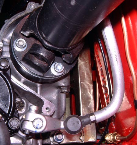 Once attached to the gearbox actuating rod it looks like this. You can see the
actuating rod bending around the propshaft which is at the top of the photo.
Once attached to the gearbox actuating rod it looks like this. You can see the
actuating rod bending around the propshaft which is at the top of the photo.
The rod is 1/2" solid aluminium and one of the slight worries is that bending it like is going to cause some undue fatigue at some point. I guess I'll just need to keep a careful eye on it. I did wonder about welding some sort of strengthening diagonal across that bottom bend, which is about 90°. However, I think I'll ignore it for now. It should be the case that it's fairly easy to take out the rod as it should involve removing the gearbox actuator arm and unbolting the rose joint that will exist at the top of the rod.
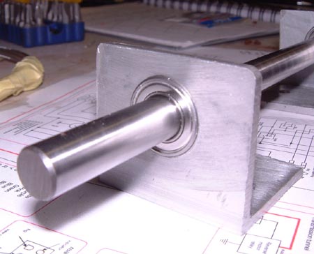 The next
thing to do was to make what is essentially a widened bell crank. This will be implemented as a rotating rod with
a couple of cranks connected to it. One of this will connect to the top of the actuator rod, the other will connect
to a rod going to the paddles themselves. (Not that they exist yet.)
The next
thing to do was to make what is essentially a widened bell crank. This will be implemented as a rotating rod with
a couple of cranks connected to it. One of this will connect to the top of the actuator rod, the other will connect
to a rod going to the paddles themselves. (Not that they exist yet.)
A while ago I bought some natty little sealed ball bearings and some 10mm diameter stainless rod to use for the shaft. I assembled all this with some lumps of ally angle to make bearing supports with and bolted it to the top of the pedal box. If you click on the photo you can see a closeup of one of the bearings themselves.
The idea is to make a crank up using some stainless steel and connect the intermediate shaft to the actuator rod, which you can see sticking up on the right of the photo, using this crank and a small rosejoint. I've done a stack of calculations as to how long this crank will need to be but I'll probably still put a load of intermediate connection points on it. There will be a similar crank at the other end of the rod to connect to the paddle actuators.
I've not yet decided how I will attach the cranks to the shaft. It's made out of super hard stainless steel and is actually pretty difficult to work. (I couldn't cut it with a hacksaw at all, and had to use a cutting disc to cut off the right length for the job here.) Hence, I might just weld the cranks directly to the rod.
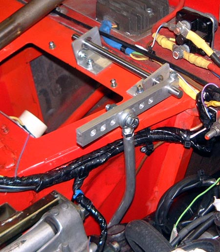 This evening I made the first of the cranks that attach to the gearchange intermediate
shaft. Some of us on the cam7 list spent a while today talking about the best way to attach the crank to the shaft
and I just ended up splitting the end of the crank (which I decided to make 10mm aluminium after buying the stainless
steel I originally intended to use) and bolting it around the shaft. Obviously, this has the problem that it's
not a positive engagement and there might end up being some slip there. However this could well be easily solved
by putting in a grub screw and machining a small pit in the shaft to locate the point on the end of the grub screw.
This evening I made the first of the cranks that attach to the gearchange intermediate
shaft. Some of us on the cam7 list spent a while today talking about the best way to attach the crank to the shaft
and I just ended up splitting the end of the crank (which I decided to make 10mm aluminium after buying the stainless
steel I originally intended to use) and bolting it around the shaft. Obviously, this has the problem that it's
not a positive engagement and there might end up being some slip there. However this could well be easily solved
by putting in a grub screw and machining a small pit in the shaft to locate the point on the end of the grub screw.
This would make things a bit less flexible though. At the moment I can adjust the position of the actuator on the splines of the gearbox gearchange shaft, the length of the actuator rod (either using a hacksaw or by screwing that little rosejoint at the top in and out), the length of the cranks (that's why there's a load of holes in this one) and the attachment point on the paddles themselves.
One thing that is very obvious already is the positive nature of the change. Pushing up and down on the end of the crank the change feels really nice and clunky, which the previous cable and lever job didn't. I do remain, though, slightly concerned that with the small amount of movement that I'll want in the paddles themselves that I might end up forces that are bit too high on the various mountings. However, other people's versions of the same sort of things seem to work fine so I guess I'll just wait and see. At the moment it's going fine, although there's a lot of aluminium swarf building up in the bin in the garage...