 I've not updated this page for a couple of days, but I have been putting in
a bit of time on the gearchange. Today I think I've completed it, barring the usually tidying up and minor fettling.
I've not updated this page for a couple of days, but I have been putting in
a bit of time on the gearchange. Today I think I've completed it, barring the usually tidying up and minor fettling.
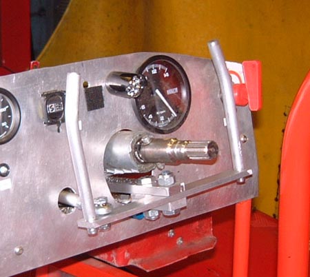
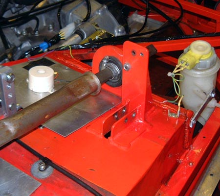
I spent ages working out how to do the "hinge" for the levers themselves and ended up with the arrangement shown here. There's actually another of those little ball bearings inside the bif wodge of aluminium just under the column and as a consequence things seem to move fairly smoothly. I might actually modify the levers themselves (the vertical bits) when I know a bit more about how it works.
The hinge is actually attached to a lump of 1" x 3/8" aluminium bar which is held around the column by
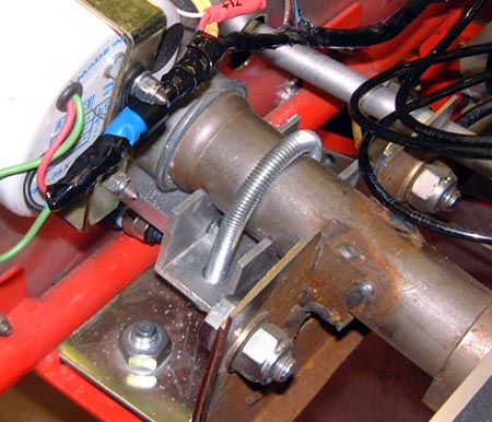 this contrivance. This is made from a piece of aluminium U section which is clamped around
the column with a bent piece of M8 studding. It certainly seems pretty firm but I guess only time will tell.
this contrivance. This is made from a piece of aluminium U section which is clamped around
the column with a bent piece of M8 studding. It certainly seems pretty firm but I guess only time will tell.
You can just see the actuator rod itself at the top of this photo. It goes through and connects to another crank at the end of the intermediate shaft.
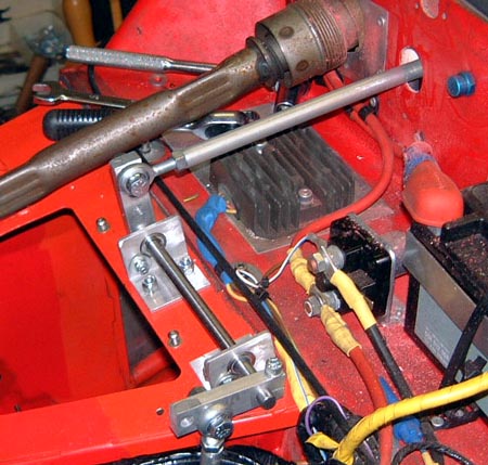 Like this. You can probably see that I've cut down the length of the output
side crank after fiddling around with seeing what the change was actually like. Obviously I can't really tell yet
but it does seem pretty decent at the moment. It will, I think, need some getting used to though, especially the
bit about using a different lever to change up from down.
Like this. You can probably see that I've cut down the length of the output
side crank after fiddling around with seeing what the change was actually like. Obviously I can't really tell yet
but it does seem pretty decent at the moment. It will, I think, need some getting used to though, especially the
bit about using a different lever to change up from down.
The assumption is that I will always change by pulling the lever towards me. (Although the whole approach means that you could push it if you wanted to.) To change up I will pull the right hand lever and to change down pull the left. I spent a while trying to decide which was best and I came up with mostly spurious reasons why this was the right way round. I could probably be convinced that it was wrong though.
Onto more mundane matters I booked the medical that I need to get to renew my licence with my doctor earlier this week. Unfortunately my diary clashed all over the place with his and I can't manage to get there for a couple of weeks. I hope that will, all the same, be not too late to go through all the formalities at the MSA. I might give them a ring to check...
I haven't updated this page for a few days. I have been doing some stuff which has been going fine but today I've gone into a bit of a decline.
First of all, I've spent a while on the subject of gear indicators. If you haven't been listening the plot is roughly like this:
- I installed an after market gear indicator which is great apart from the facts that a) it doesn't work properly and b) you can't see it in bright daylight anyway.
- I took that out and wondered about building some bit of electronics with a small display that would do the job properly.
- I realised that the DL-1 generates a continual data stream which tells you what things it's measuring. That is, there's already an interface to things like speed sensors and the DL-1 generates the information in the form of an easily assimilable serial data stream. So, I set out on designing a bit of hardware that would interface to this serial data stream.
- Anthea pointed out that as all I needed was a small box with a screen and a serial port then there plenty of PDAs that could do this job without having to actually design and build the hardware. The development environments would be better too.
 So, I've
spent the last few days spare time looking into programming a palm PDA (which I happen to have) to do this job.
It's well on the way now and this is a picture of the current display. (Although, it's actually an emulator on
a PC screen which is used to make development a smidgeon easier. It looks exactly the same on the real thing though.)
So, I've
spent the last few days spare time looking into programming a palm PDA (which I happen to have) to do this job.
It's well on the way now and this is a picture of the current display. (Although, it's actually an emulator on
a PC screen which is used to make development a smidgeon easier. It looks exactly the same on the real thing though.)
All that stuff at the top left's for debugging purposes and I don't really think much of the rest will be useful other than the big gear number. It's also calculating the amount of time that the car's been running. This is useful for races which are essentially for a fixed amount of time. I'll probably have to use some bigger numbers though.
The other thing that I could do with this is to use the whole caboodle for lap timing. The DL-1 has an input for a timer beacon and the output data stream records when the beacon is passed. That would allow me to get rid of the separate lap timer and I could probably display something a bit more useful, most obviously something about the trends in lap time over the last 2 or 3 laps.
 So, flushed with success I staggered back into the garage and did some fettling in the cold for a change.
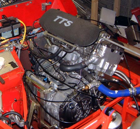
First job was to put the carbs back on the engine which took a surprisingly long time.
So, flushed with success I staggered back into the garage and did some fettling in the cold for a change.
First job was to put the carbs back on the engine which took a surprisingly long time.
I was then looking at getting the throttle pedal back on. Now, I had been aware that I would have to have the pedal at a different angle so as to match the moved brake and clutch pedals. However, when I came to do this, it wouldn't go due to the pedal binding on the top of the pedal box.
Rats!
I had wondered whether this would be an issue but had forgotten to check before I painted the pedal box and got it all neat again.
 The problem is going to have to be resolved by cutting this turret thing off
the top of the pedal box and moving it forward by the same amount that I've moved the brake and clutch pedals.
The problem is going to have to be resolved by cutting this turret thing off
the top of the pedal box and moving it forward by the same amount that I've moved the brake and clutch pedals.
A real shame that as it's going to mess things up again, just when they were getting neat again.
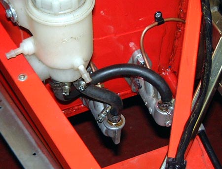
However, there's a bigger problem which I noticed at the same time. I must admit that this is something I knew about ages ago and should have sorted. The problem is that because I've got the pedals much more upright than normal short-legged people would have means that the pivot that drives the master cylinder pushrods is really a bit above the centre line of the master cylinders. However, it used to work sort of OK so I just left it alone.
But, all the work I've done on the pedal box seems to have exacerbated the problem, probably because I've managed to get the mountings for the master cylinders in a smidgeon lower than I had them before. I had tried not to do this, but I guess I must have screwed up.
 This means that I'm going to have to take the master cylinders out and change
their mountings. I shall probably have to do this by bolting/welding a mounting plate in about 15mm above where
the existing mounting are. Annoyingly this is going to add more weight as it will have to be a fairly substantial
plate. What's worse it that it will necessitate a lot of drilling and messing around on this reasonably neat pedal
box.
This means that I'm going to have to take the master cylinders out and change
their mountings. I shall probably have to do this by bolting/welding a mounting plate in about 15mm above where
the existing mounting are. Annoyingly this is going to add more weight as it will have to be a fairly substantial
plate. What's worse it that it will necessitate a lot of drilling and messing around on this reasonably neat pedal
box.
Even worse I suspect I'll have to take the engine out again. Although, as I sit here thinking about it I'm not sure that that's the case.
Probably the first thing to do is to get a suitable lump of steel and cut some holes in it for mounting the master cylinders (a bit like the one that you can already see welded to the front of the pedal box). Unfortunately, the only bit of suitable steel I can find is 3mm stuff, which is bit more suited to bridge building than this.
Oh well....
I'm a bit late, again, in updating this site. I have to admit that I'm feeling a bit pressured about the new season just around the corner and the amount left to do. After all, I don't know yet if the new engine actually works!
The 750 Motor Club have now published the regs for next year and there's a first attempt at the race calendar. The latter is available on their site here. The new regs are going to mean a couple of mods to my car, in particular to make the hole over the air inlet filter point forwards somehow. But, that was something I was thinking about anyway. I would like to find the time to make a proper airbox but I'm not at all sure that I've got the time.
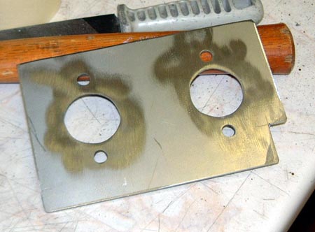 I've been getting on with sorting out the pedal box. First of all, I cut out
this plate for mounting the master cylinders on.
I've been getting on with sorting out the pedal box. First of all, I cut out
this plate for mounting the master cylinders on.
Then I had a master stroke, and realised that I didn't need to take the engine out, I could just support it on the hoist and take the engine mounting out that's in the way.
With that done I took the master cylinders out, again, welded/bolted this plate in place so that the cylinders are 20mm higher than they were before, and put the engine mounting back. I hope to put the master cylinders and so on back again this evening. I may well remake some bits of the brake lines though, as they are getting a bit bashed about by being repeatedly bent out of the way.
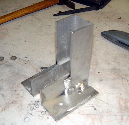 With that done, I turned my mind to the throttle pedal. I cut off the existing
"turret" above the pedal box and enlarged the hole in the top of the box to allow the throttle pedal
to be moved forward and still move properly. I then needed to make something like the turret and decided to use
some chunky aluminium U section that I've got around. I made this device as seen here by welding a chunk of U section
to two angled bits which were actually made by slicing off one leg of the U section.
With that done, I turned my mind to the throttle pedal. I cut off the existing
"turret" above the pedal box and enlarged the hole in the top of the box to allow the throttle pedal
to be moved forward and still move properly. I then needed to make something like the turret and decided to use
some chunky aluminium U section that I've got around. I made this device as seen here by welding a chunk of U section
to two angled bits which were actually made by slicing off one leg of the U section.
My aluminium welding is nothing to write home about but I think this is OK, I may bottle out and stick some bolts through as well though.
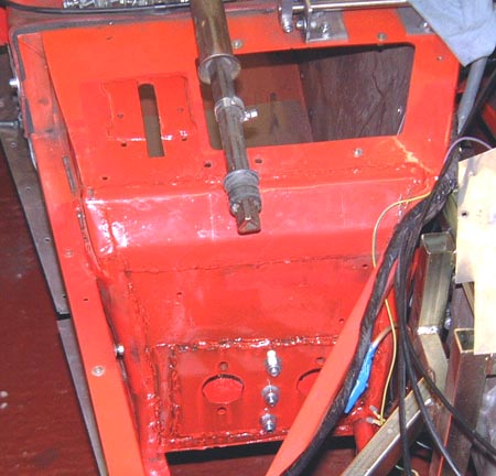 I then tarted everything up again by waving some red hammerite around. I haven't actually
put the turret back as I want to wait until I've got the other pedals in before positioning the throttle pedal.
I then tarted everything up again by waving some red hammerite around. I haven't actually
put the turret back as I want to wait until I've got the other pedals in before positioning the throttle pedal.
Those extra bolts, by the way, are to make doubly sure that the centre of the plate (which is not welded, of course) doesn't get a chance to flex away from the rest of the box. I'm pretty sure it would be OK without them but what the hell?
Hopefully this evening I can get all this area back together. As I've ordered some new gaskets for the exhaust header mountings I might even be able to try running the engine which would be quite a relief. One problem, though, it that I've noticed the sump plug is leaking slightly, which is probably a consequence of not replacing the gasket...