 I wanted to have a bit of a go at the car this weekend, as things have been
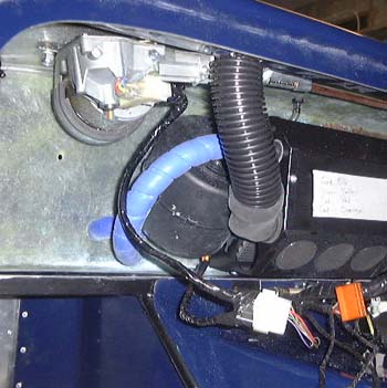
languishing a bit for a while. First thing was to sort out the wiring for the wiper motor. Having mounted the scuttle
it was obvious that the existing wiring wasn't going to reach. So, I extended it with the aid of a multi-connector
that will allow the scuttle to be removed at some point in the future. I bought a lot of these connectors a while
ago, as I want to make it possible to remove the dash without huge re-wiring; the connectors are key to this plan.
I wanted to have a bit of a go at the car this weekend, as things have been
languishing a bit for a while. First thing was to sort out the wiring for the wiper motor. Having mounted the scuttle
it was obvious that the existing wiring wasn't going to reach. So, I extended it with the aid of a multi-connector
that will allow the scuttle to be removed at some point in the future. I bought a lot of these connectors a while
ago, as I want to make it possible to remove the dash without huge re-wiring; the connectors are key to this plan.
I checked out that the wiper worked after this. I'm not entirely sure that the wiper blades will sweep enough of the screen, but that can wait to be checked later.
I used the same connector for wiring up to the heater fan, which has a three speed fan. At some point I will have to decide which speeds the two speed heater fan switch will set off.
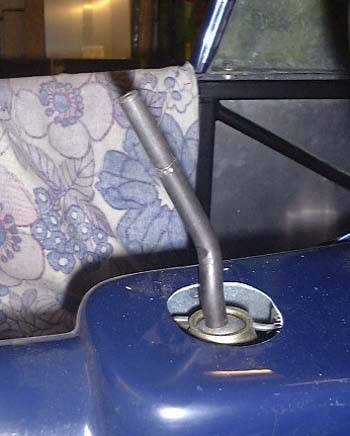 A while ago I bought a gearknob for the car, and I thought I'd have a bit of fun fitting
it. The first thing to do was to reduce the diameter of the left over bit of the gearlever, which I stunted a while ago. It looked as though the remaining bit of the upper bit
of the gear lever was actually just a sleeve over the lower bit. So it turned out after a bit of work with the
grinder. Once that was removed the gear lever was exactly 12.7mm (0.5" in old money) in diameter.
A while ago I bought a gearknob for the car, and I thought I'd have a bit of fun fitting
it. The first thing to do was to reduce the diameter of the left over bit of the gearlever, which I stunted a while ago. It looked as though the remaining bit of the upper bit
of the gear lever was actually just a sleeve over the lower bit. So it turned out after a bit of work with the
grinder. Once that was removed the gear lever was exactly 12.7mm (0.5" in old money) in diameter.
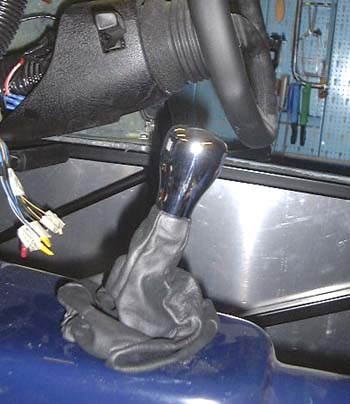 This was the perfect diameter for the new gear knob, for which I also bought a leather
gaiter that screws in to the bottom of the knob, meaning that that problems I had making the Westfield one fit
should be a thing of the past.
This was the perfect diameter for the new gear knob, for which I also bought a leather
gaiter that screws in to the bottom of the knob, meaning that that problems I had making the Westfield one fit
should be a thing of the past.
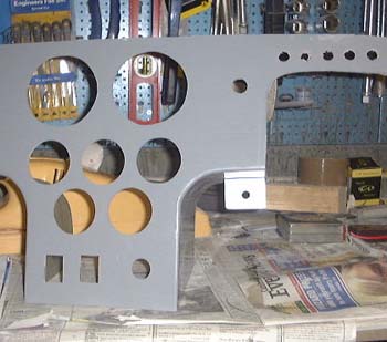
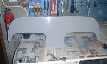 After that I started on the dash itself. Initially it was just a blank, although marked out for various
different steering column cutouts. The blank has got some studs embedded into the GRP for mounting the dash into
the scuttle, although it's not clear how easy it's going to be to do up the fixing nuts.
After that I started on the dash itself. Initially it was just a blank, although marked out for various
different steering column cutouts. The blank has got some studs embedded into the GRP for mounting the dash into
the scuttle, although it's not clear how easy it's going to be to do up the fixing nuts.
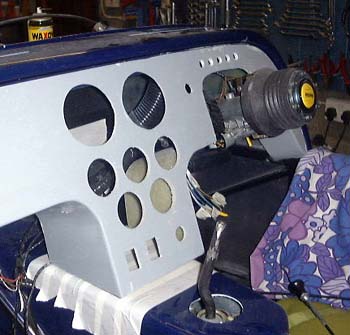
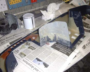
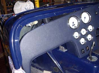
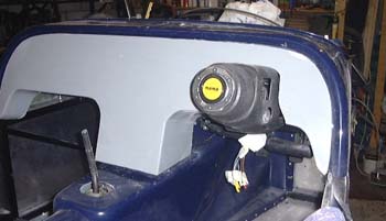 After a lot of sawing and grinding, it fitted like the photo here. The sort of chamfer
at the bottom right is to enable access to the key, but it still isn't wonderfully successful.
After a lot of sawing and grinding, it fitted like the photo here. The sort of chamfer
at the bottom right is to enable access to the key, but it still isn't wonderfully successful.
Also, as I suspected, getting access to the mounting lugs is horrendously difficult for one of the lugs and just impossible for another. I'm wondering if some pretty bolts just going straight through wouldn't be a better idea; at least you could do them up from the front.
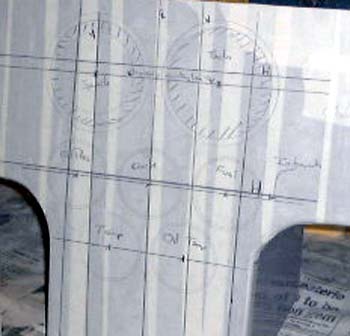
 Now I have to work out where to put the instruments. There's no real guide as to how to
do this, and what it obvious is that they will have to go in the middle of the dash, although there's probably
room for the warning lights in front of the driver. The problem is there's more than one way to arrange them, so
I made some paper simulations and tried them in various places. To check all this I sat in the car and it felt
quite snug in there, although of course there's no seating yet.
Now I have to work out where to put the instruments. There's no real guide as to how to
do this, and what it obvious is that they will have to go in the middle of the dash, although there's probably
room for the warning lights in front of the driver. The problem is there's more than one way to arrange them, so
I made some paper simulations and tried them in various places. To check all this I sat in the car and it felt
quite snug in there, although of course there's no seating yet.
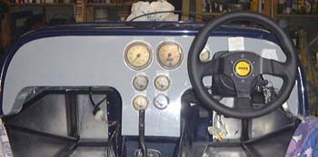
There are two layout possibilities in the photos here, a symmetric and asymmetric one.
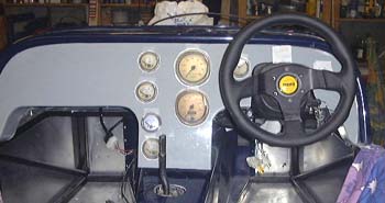 There are quite a lot of instruments here, including:
- Tachometer
- Speedometer
- Fuel gauge
- Water temperature
- Oil pressure
- Oil temperature
And, last but not least, a clock! This might seem a bit odd but I always really missed not being able to easily read the time in the Westfield.
Of course, there are a few switches too, and a manual choke to fit in somewhere!
Next time, I'll have to work out how I really want to make it look.
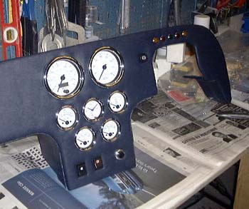
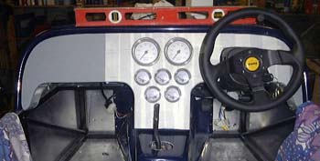 I wasn't totally convinced about the two previous dash layouts, so I decided to have another
try. This time I marked things out properly and ended up with this next suggestion.
I wasn't totally convinced about the two previous dash layouts, so I decided to have another
try. This time I marked things out properly and ended up with this next suggestion.
Everyone (the rest of the household is involved in this decision) is happier with this one so this is the way we're going for the moment. (Although, everyone on the Dax list seems to think different....)
You'll notice that there's masking tape all over the dash now, this is for properly marking it out. I found it really difficult to establish some sort of datum from which to do all the measurements for this layout. The dash itself is a very odd shape, and when you look closely at it you realise that it's nothing like symmetrical anyway. The only way I could get something approaching a start on this was to put the dash in the car and use a spirit level (which you can still see) to establish a "true" horizontal and vertical. I could then work from these. All this too ages to do with any confidence of it being right.
 Of course, working out where these instruments go has involved extensive measurement and trigonometry.
Unfortunately, Tom's nicked my calculator so I've had to keep running back and forth to the PC.
Of course, working out where these instruments go has involved extensive measurement and trigonometry.
Unfortunately, Tom's nicked my calculator so I've had to keep running back and forth to the PC.
While rooting around with all this, Anthea suggested that it might be possible to hold the dash in with the two studs I can get at, and some velcro. A lot of the Westfield is held together with velcro, quite successfully, so that might be a good suggestion. I am intending to make the bottom of the "centre console" bit of the dash mount firmly to the tunnel, so with the velcro it might well be quite firm. So, for now I'm assuming that this will work.
I've also decided to try and hide the choke adjustment under the steering column somewhere. It's just too ugly to be allowed out elsewhere...
Tonight I finished marking out the dashboard. Having decided that that narrow part of the dash that is just above the steering column is rather thin and floppy, I added some GRP to it in an attempt at getting it to be a bit more robust. We'll see what it's like tomorrow.
 In what might turn out to be the last frenzy of GRP hacking, I cut out all the holes in the instrument
panel tonight. Hence, I'm coughing due to ingesting too much dust. I now know why that Dax factory is full of dust
and the Westfield one isn't.
In what might turn out to be the last frenzy of GRP hacking, I cut out all the holes in the instrument
panel tonight. Hence, I'm coughing due to ingesting too much dust. I now know why that Dax factory is full of dust
and the Westfield one isn't.
With luck I'll be able to look at starting to cover the dash tomorrow. This is going to be a bit tricky due to the intensely 3D nature of the beast.
I think I've also worked out where to put the choke cable, so watch out....!
At the weekend, it was on with the dash again, but before that we made a trip down to Dax to order some final
bits. We (well, Anthea) spent ages trying to decide on colours. After all that was done, we ordered the seats (I'm
getting the Dax 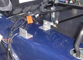 squab seats as that gives a bit more cockpit room), some carpet and a tonneau
cover. We also bought some seatbelts which they had in stock. These are the aircraft buckle variety, which are
much easier to get on and off and the four belts can be clipped in separately.
squab seats as that gives a bit more cockpit room), some carpet and a tonneau
cover. We also bought some seatbelts which they had in stock. These are the aircraft buckle variety, which are
much easier to get on and off and the four belts can be clipped in separately.
Back at the house, I made up some brackets to support the bottom of the "console" bit of the dash. These are just some bits of aluminium angle, rivetted to the front part of the tunnel cover and with a rivnut let into them so that a bolt through the side of the dash has somewhere to go.
With the dash back in place it was much firmer, and I think the Velcro approach to fixing the middle of the dash will work fine.
 I had finally decided that I was going to have to mount the choke cable on the dash, as
that was the only way it was possible to reach it. However, to make it easily removeable (so the dash can be taken
out) I decided to make a small aluminium bracket and attach it to the dash using yet more rivnuts. The dash is
rather thick GRP, again, but this time it helps to give something solid for the rivnuts to grab hold of. Unfortunately,
in fiddling around with the choke cable I dropped the little gadget that makes the adjustment "stiff".
I'll have to see about getting another one.
I had finally decided that I was going to have to mount the choke cable on the dash, as
that was the only way it was possible to reach it. However, to make it easily removeable (so the dash can be taken
out) I decided to make a small aluminium bracket and attach it to the dash using yet more rivnuts. The dash is
rather thick GRP, again, but this time it helps to give something solid for the rivnuts to grab hold of. Unfortunately,
in fiddling around with the choke cable I dropped the little gadget that makes the adjustment "stiff".
I'll have to see about getting another one.
 After that I set about covering the dash. I have some vinyl that I bought for the Westfield
that I was going to use, and I bought some thin foam at last year's Stoneleigh show to pad it a bit. So, I set
to with Stanley knife, glue and so on and eventually (this cuts a long story very short) I had it mostly covered.
The problem with the Dax dash is that is it a rather 3D shape, even the flat dash, so it needs more that one piece
of vinyl to cover it. I'm not sure I've managed to do the bits that go round the knee-holes too well, but they
will do I think. (The photo here shows a lot of glue on one of these bits!)
After that I set about covering the dash. I have some vinyl that I bought for the Westfield
that I was going to use, and I bought some thin foam at last year's Stoneleigh show to pad it a bit. So, I set
to with Stanley knife, glue and so on and eventually (this cuts a long story very short) I had it mostly covered.
The problem with the Dax dash is that is it a rather 3D shape, even the flat dash, so it needs more that one piece
of vinyl to cover it. I'm not sure I've managed to do the bits that go round the knee-holes too well, but they
will do I think. (The photo here shows a lot of glue on one of these bits!)
 Finally, as I wanted to see what it looked like, I tried fitting the instruments. Of course,
quite a few of the holes turned out to be very slightly too small but after a bit of work with the Dremel they
were fine.
Finally, as I wanted to see what it looked like, I tried fitting the instruments. Of course,
quite a few of the holes turned out to be very slightly too small but after a bit of work with the Dremel they
were fine.
After all this, I can perhaps get on with the wiring next, although I still need to glue down the bits of vinyl that stick through the instrument holes.
 Tonight, I started wiring it up. First of all all the instruments were properly mounted
after the remaining bits of loose vinyl were stuck down. Then, I covered the instruments with masking tape so that
I can put the dash down on its face and started wiring it all up.
Tonight, I started wiring it up. First of all all the instruments were properly mounted
after the remaining bits of loose vinyl were stuck down. Then, I covered the instruments with masking tape so that
I can put the dash down on its face and started wiring it all up.
I finished two of the connectors for the dash today (you will remember that I'm trying to make the dash removable). The first is for the switches: fog, heater fan and starter. The second, which is in the photo, is for the warning lights. I reckon there will be two more connectors after this, one of which will be the one that is part of the loom anyway.
Some more dash wiring this evening, it's now mostly done. (Doing this wiring is nice as I can do it sitting at the kitchen table in the warm.) There's only a few bits left to do now, and it occurred to me, as I was putting everything away, that I could connect up the dash and see if at least something worked.
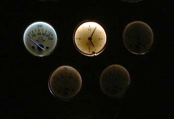
So, I plugged it in and, sure enough the clock worked. Cool! I then realised that I could turn on the car lights (although only the number plate light works at the moment) and I should be able to see the instrument illumination. So, I turned off the garage lights and turned on the car lights and...the dial illumination can only be described as pathetic! The illumination is uneven and dim to the point of the dials being essentially unreadable. Although I doubt they can test this at SVA it clearly isn't satisfactory. I've emailed the nice people at Greengauges so we'll see what they say. In the past they've been very good about the odd support query, such as when I munged the speedo sensor.
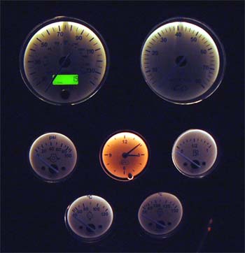 I finished the illumination wiring tonight (only half of it was done last night). This
meant I could look at the overall illumination situation. To be honest, it looked pathetic, not the effect I was
aiming at at all. Oddly, the clock is rather a different colour from the rest of the instruments, and much more
readable.
I finished the illumination wiring tonight (only half of it was done last night). This
meant I could look at the overall illumination situation. To be honest, it looked pathetic, not the effect I was
aiming at at all. Oddly, the clock is rather a different colour from the rest of the instruments, and much more
readable.
The photo here gives you some idea what is going on. It certainly emphasises the difference in the clock from the rest of the instruments.
I had a reply from Greengauges today. It was rather terse, just a note that they'd forward it to "their manufacturing partner", who are CAI. I have this little niggle that I'm being fobbed off.
 Well, Greengauges amaze me. Yesterday, having seen the picture above (or at least a higher
quality one that I sent them) emailed me to say that they were going to refund all my money, and that I could keep
the instruments for day time use if I wanted them. However, I would rather fix them somehow, and in any case I
would feel very guilty about this. Still, today they emailed me to say that they had done this anyway.
Well, Greengauges amaze me. Yesterday, having seen the picture above (or at least a higher
quality one that I sent them) emailed me to say that they were going to refund all my money, and that I could keep
the instruments for day time use if I wanted them. However, I would rather fix them somehow, and in any case I
would feel very guilty about this. Still, today they emailed me to say that they had done this anyway.
So, still feeling guilty, I decided to try a couple of experiments. I went to Halfords and bought some different illumination bulbs. The ones that are in the smaller instruments are 1.2W. I got some of the same size at 2.2W and 5W dissipation. As you would expect, the 2.2W ones didn't make very much difference at all. However, the 5W ones are great, making the instruments I tried them in much easier to read. Unfortunately, things get a little warm, but I'll ask Greengauges what they think. There's actually 5 instruments in this photo, but only the two at the top left have got the 5W bulbs in them. Unfortunately, the speedo and tacho have a different size of bulb in them which may not be as easy to find in a larger power version.
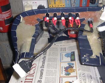
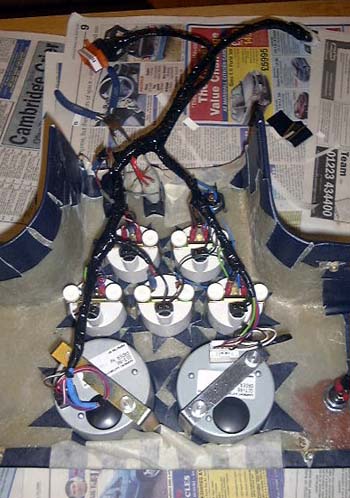 Following that I finished wiring the dash, the back of which you can see here. At the top of the photo
you can see two of the connectors that allow the dash to just plug into the car.
Following that I finished wiring the dash, the back of which you can see here. At the top of the photo
you can see two of the connectors that allow the dash to just plug into the car.
There are three connectors in all, so the next thing to do is to put the other bits of the connectors into the car. So, I wired up the one that connects to all the warning lights and plugged the dash back in again. Now I could turn on the ignition and see the charge and low oil pressure lights come one.
With luck, tomorrow I'll get the wiring in the car done for the back of the dash, which will mean that this bit is done, barring messing about with the instrument illumination.
 I finished off all the dash wiring, including all the bits on the car. Now all the instruments
and controls worked with was nice, although the scuttle and dash are not bolted in at the moment. One reason for
this is that I need to make a gaiter for the handbrake, and it's a lot easier to get to it with the scuttle off.
I finished off all the dash wiring, including all the bits on the car. Now all the instruments
and controls worked with was nice, although the scuttle and dash are not bolted in at the moment. One reason for
this is that I need to make a gaiter for the handbrake, and it's a lot easier to get to it with the scuttle off.
The final problem to solve with the instruments relates to the fuel gauge. The problem is that the Dax sender is the opposite "sense" to that used by Greeengauges. This means that the gauge works the wrong way round. That is, it displays full when the tank in empty.
Unfortunately adjusting this in any electrical way is rather tricky. Although it's perfectly possible to design a bit of electronics to do this, in fact, I've done it, that seems overkill. I ended up doing what everyone else face with this has done.
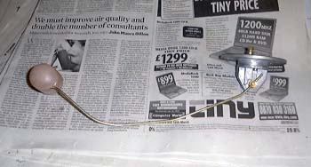 This is to take the existing sender, which looks like this:
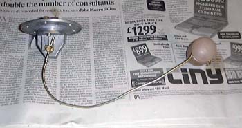 ..and to modify it by bending the float wire completely around the resister block, like
this:
..and to modify it by bending the float wire completely around the resister block, like
this:
It's a bit of a brute force solution, to be honest, but it does seem to work.
in case you've got to this frame directly and can't get out, go here.