This has been a busy weekend on the car front. I spent most of Saturday helping Dan fettle his ZX9R engined Striker.
Yesterday we went up to Stoneleigh for what's becoming a traditional pilgrimage. This time I had a couple of ulterior motives. First of all, I wanted to put the Dax somewhere prominent with a for sale sign on it. That was a complete waste of time as no-one approached me about it. Mind you, it was a great drive up there. Adrian was also with us and he commented when we got there about the absurd acceleration of the Dax compared to his Pell Genesis. I told him I was pretty sure that I'd never actually pushed the pedal all the way to the floor.
I also wanted to buy a couple of things for the Fury. Some things I couldn't find, but I did manage to buy all the lights I needed with the exception of a fog light. I managed to get them for a very nice price from Stafford Vehicle Components. Hopefully, they'll fit OK.
 Today I narrowly decided not to go to the RGB race at Brands Hatch but got on
with the car. Now the dash is all done I can get on with the rest of the wiring. First of all I installed the battery
in the middle of the scuttle, I had been wondering where to put the battery but decided that mounting it low would
only require lots more heavy cable anyway so it was probably best up there near to the things it would be connected
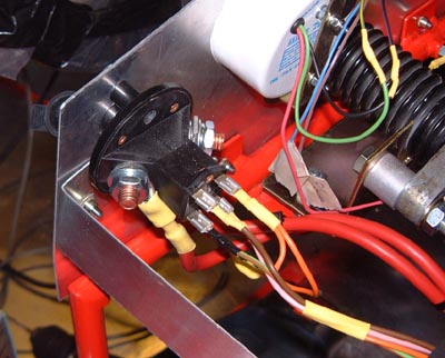
to. I could then wire up the isolator switch on the end of the dash. I actually tapped the mounting holes in the
switch so that it's a bit easier to remove. Due to having to mount the switch on the dash it rather ruins my plan
to make the dash simple to remove by using loads of connectors if the isolator is wired in and also part of the
dash. (You can't run the battery cables through a connector, you see, at least one that I want to put on the car.
However, it's now pretty easy to remove.
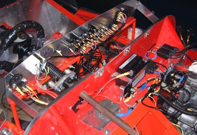 Carrying on with the wiring I mounted the regulator on the scuttle, this time
on a sheet of aluminium and with some heat sink compound under it to allow the aluminium to help cool it a bit.
These regulators are supposed to be a weak spot of the bike electrics and the lack of airflow inside the engine
compartment, compared to a bike, is bound to be an issue. I'm actually wondering about fitting a small fan to it,
although DC fans are largely spawn of the devil.
The starter relay is next to the battery and the CDi and the coils are on the left. All of this lot is now wired up to the engine properly, including the HT leads which the previous owner of the engine had already modified to make suitable for bike-engined car fitting.
With that all done there's a fairly small amount of loose wires hanging around, with the exception of the lighting wiring and the extra bits and pieces needed for the electric reverse.
Looking back, there's a lot of wiring been done the last few days. From just having a few bits of loom in it, the car now seems to have loads of wires, the photo above shows quite a lot of them. I think that now, all of a sudden, I can see some light at the end of the tunnel. Perhaps now's the time to put in some race entries and start thinking about track-day shakedowns..
Having got that feeling that things are at least getting towards being able to see the pre-anti-penultimate lap on the horizon, I spent a while today updating the to-do and to-get lists. Hopefully. these are now pretty close to everything that's left.
 Later on in the day, I spent a short time trying to get the wiring finished.
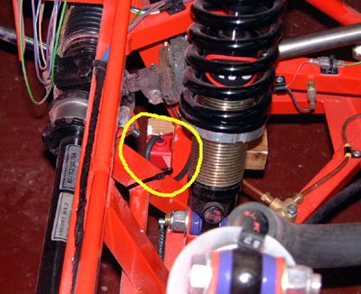
As part of this I mounted the transponder at the front of the car and wired up its power supply. You can just about
see the transponder in this photo, attached to the front of the chassis and pointing down at the road.
The only bits of wiring now are those to the neutral switch and oil pressure warning switch on the engine, and the wiring for the lights that are not yet attached to the bodywork.
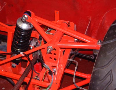 Finally, I've resolved the issue about why the wheels stick out beyond the bodywork!
Well, not me exactly! Martin Bell sent me an email saying that tubular front rockers arms on IRS chassis should
be attached to the inner of the mounting holes! Apparently, I'll probably need to chop a bit off the thread on
the lower ball joints so that I'm not permanently running loads of negative camber, but that can wait until I've
got the car back on the ground.
So, I moved the rockers about and it certainly seems to fit better that way. I assume that Martin knew I'd got them wrong by looking at this web page, so at least all this late night hacking has some use!
 Not much time this evening, so I thought I'd just do a couple of little things.
First was to finish the wiring to the engine itself. The first bit of this was the connection to the neutral switch.
This is just by the output sprocket and consequently dead difficult to get to on the car. However, after much grovelling
on the floor I got it done. I then connected up the wiring to the water temperature sender and the oil pressure
switch. I am not actually planning on using the former as I have a mechanical temperature gauge but there's no
harm putting the wiring in in case I use it.
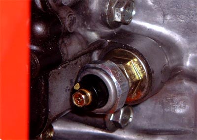
Getting at the oil pressure switch was useful as I need to get an adapter so as to fit the pressure gauge capillary. To do that I need to know the thread used for the pressure switch at the moment. After much grovelling around under the car I got the pressure switch out (that's it on the right). Attacking it with a thread pitch gauge showed that it was, as I thought, 1/8 BSP (28 turns per inch as opposed to the 27 turns per inch of the very similar 1/8 NPTF). I'm not sure why the world needs so many thread systems, especially those for pressure connections which are of quite Byzantine complexity.
 After all that (which took much longer than it takes to write about it!) I moved
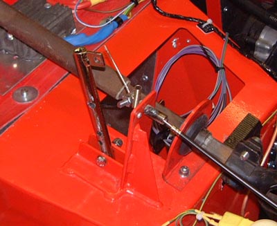
onto one of the other outstanding issues and started changing the throttle pedal so that it has a little more travel.
I'll finish this next time though.
 Only time for a very short visit to the garage this evening.
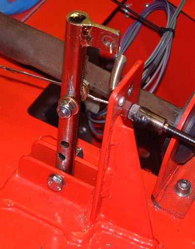
I finished off moving the cable attachment point on the throttle pedal lever. It's now about 50mm below the "normal" position and this seems to give a better ratio. However, only time will tell. The only thing left to be done here now is to construct some form of throttle pedal stop. As it is it is just the carbs that stop the cable which doesn't seem clever.
What I need to do next here is to construct some form of throttle pedal stop. The best approach seems to be a fairly chunky bolt head behind the pedal but I need to have a think.
Finally, I added another electrical connector for the front right lighting. A connector seems sensible so that the bonnet can be removed.
This evening I spent a while making a device that I intend to use for connecting the water temperature sender into the engine plumbing, most of the pipes for that arrived today too. This device will need welding together though, so I'm off to Adrian's house tomorrow to borrow his mega-TIG welder to have a go at it. I'll probably just blow a huge hole in it and have to start again.
Then I went on to finalising the wiring. Some battery wire terminals that I needed arrived today too so I could make the battery earth strap. I made this and connected it up, so the only thing between me and some lights on the dash was the isolator switch.
Next up was to add some more connectors to the loom for the lighting in the corners of the car. However, when I got to the back of the car it's apparent that I must have had some sort of fit in that I haven't labelled the wires properly. The problem is, there seem to be far too many wires which seems odd. Oh well, I was reduced to buzzing it out again.
 One easy way to check some of this was to actually turn the car on. I spent
a while wondering whether to do so and eventually turned on the isolator. With the appropriate fuse in place I
even got some of the dash lights to come on. There is a small problem, however, in that I'm not sure the flasher
unit is working properly. However, this is probably just the result of not having any load on it.
The real problem then cropped up though in that there was a clonk, followed by a fizzing noise and then, clouds of acrid smoke. Obviously something was shorting out and I reached across and turned off the isolator. This made no difference at all at which point I panicked!
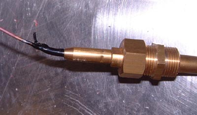
After a certain amount of flailing about I realised what was going on. The sender for the water temperature had been resting on top of the scuttle (I had been looking at it while I was making the bits of aluminium mentioned above. The sender had then dropped onto the positive terminal on the battery (for which I haven't yet made some sort of shroud) and then stacks of current flowed along the capillary pipe to earth through the dash itself. This had the effect of melting the insulating sheath of the capillary creating all the smoke. In the photo above you can see the remains of the sheath at one end.
Untunately, the instrument itself does not seem to have survived the ordeal in that it doesn't ever read below 50° now. Oh well, what an idiot.
Still. it was clear that the electrics are coming to life, albeit slowly.
 I really tried to do lots this weekend, but only succeeded partially.
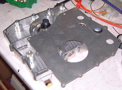
The first thing was to go to see Martin Bell and pick up some more bits. First of these was a baffled sump for the engine. As well as the baffle this is shallower and has the drain hole moved round to the side to as to not stick down.
The sump itself is the expected CNC-milled billet variety. I always wonder what happened to all the aluminium that they mill away, as there must be more of it than is left behind.
The sump came with the baffle plate (sitting on the top in this photo), a shortened pickup and a small device that apparently fits under the pressure relief valve. In a while I'll have to drop the sump on the engine and see what it all looks like. One issue is that really I should buy two sump gaskets. However, as they're apparently 14 quid each I may just use some liquid sealant.
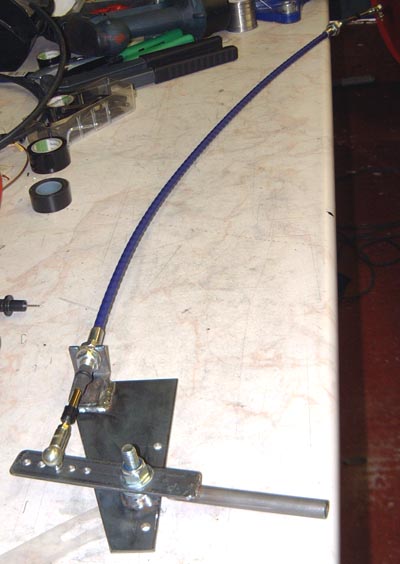 The other thing I picked up from Martin, and the reason
I went really as I want to know where stuff goes in the tunnel, was the gearchage, or at least the first part of
it. This photo is pretty poor but the nearest bit is the gear lever which is connected to a push/pull cable. There's
a little rose-joint like thing on the other end for attachment to the engine's gearchange rod.
The lever will need some sort of extension on it, but that can wait for a while
Now I've got this I can work out where it's going to go in the tunnel and also work out where the reverse actuator can go. I can also be sure that I haven't got to move any of the wiring and pipework in the tunnel.
 After going to Northampton I went over to Peterborough to
see Adrian and sponge up some of his "free" time. Adrian's got a TIG welder and, what's more, knows how
to use it! I need to make some way of getting the temperatur sender into the top hose, as the little tiny Honda
sensor isn't compatible with the capillary gauges that I've got, (And blown up!)
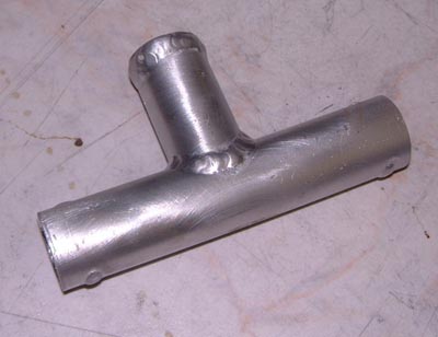
Although you can get adaptors to do this sort of thing they don't seem to come in the sort of sizes needed to fit the coolant pipes on this engine. Hence I bought some 25mm aluminium tubing and got Adrian to weld them together into this tee.
The top is actually a 5mm thick plate and I'll tap this to 3/8" BSP so as to fit the sender. I ordered a tap from these people for doing this. I'll also use this to tap a whole in the sump for the oil temperature sender which is exactly the same size as the water version.
The reason for using Adrian's TIG welder is that doing this sort of welding with my MIG welder is only just about feasible. What's more, it always seems to end up porous which is about as much use as a chocolate teapot for a water-tight cooling system.
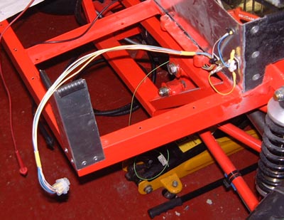 Back home again I settled back to the wiring and finished off (with a couple of very minor exceptions)
all of the wiring that's actually tied to the chassis. (That is, excluding the lights which are connected to the
bodywork.)
This photo is actually the right-rear of the car. The connector at the left is for the lights in this corner and there's also some wiring for the roll-bar mounted rain light. You can just about see the current-limiting resistor for this attached to the upright portion of the "boot".
 With that, I wanted to get on with the fuel system. I've had
a small issue for a while in that the fuel connection to the carbs is 3/8" and the connections to the pump
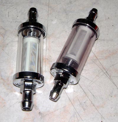
and tank are 5/16". Someone mentioned to me one way to fix this which is to hybridise two fuel filters so
as to filter and convert the pipe size in one go.
I already had a 3/8" filter sitting around so I had ordered a 5/16" one as well. Here there are. It was easy to swap around one of the end pieces giving me two filters with dissimilar connections.
I attached the fuel filter to the rear of the chassis in the appropriate place. (Although, it's not going to be amazingly accessible!)
The next issue was the fuel pump. A while ago I got hold of a fuel pump from an R1 and I just needed to find out how to use it. I worked out which way round the wires went from a wiring diagram for the R1 bike that I found on the web. The next issue was which of the two pipes was blow and which was one suck.
 So, I lashed the pump up to some wiring and poked some pipes into a fuel can and tried
it. After a certain amount of faffing about it became clear which was which. The pump is of the interrupter type
(like the Red Top pumps that are commonly seen) and certainly seemed to pump large quantities of fuel if it wants
to. One issue is how to mount the pump. In the bike it's mounted horizontally below the tank but that isn't feasible
in the car. After a certain amount of flailing around fuel pipes it seemed as though the pump would go almost anywhere.
It seems quite happy for the tank to be some way below it even.
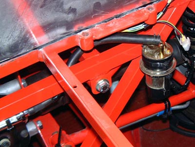
Hence, I decided to mount the pump in the position shown here, which is just behind the driver's seat. I spent a while wondering about making some fancy brackets but decided that a couple of the inevitable tie wraps would actually be better and a lot easier to do.
 So, in an effort to finish at least one of the car's systems. I then went back
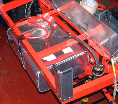
to the fuel tank which I'd trial fitted a while ago. I made a fairly substantial aluminium strap for this (although
secured at one end by more tie-wraps) and fixed it in. Experimentation shows that this tank is going to require
some modifications to the rear bodywork. I think I'll have to cut a hole of some shape in it and make some sort
of power bulge. What I might well do is panel under the complete rear suspension which I think I could also use
to cover up the exposed tank.
With the tank in (and I'll make some sort of lateral strap later as well) I put the final bit of pipework in from the feed line of the tank to the pump inlet. You can see this looping over the chassis rail in the photo. The red pipe behind is the vent line which has a valve on the end of it. This will be secured to the roll bar later.
I put a few litres of fuel in the tank and disconnected the hose at the carb end and pointed it into an empty water bottle. Then, I turned on the fuel pump using the dash, which is coming to life, as mentioned before. The pump when clunka-clunka-clunka and fuel started filling up the bottle! I put the car feed hose back and poured the bottle'c contents back into the tank. With that I could try the pump and this time the clunking went (almost completely) away after a few seconds as the float chambers on the carbs filled up.
That's all kind of satisfying as it's a complete end-to-end system on the car completed.
 So, I moved onto the cooling system. I had had to take the radiator out a while
ago when I found that the bonnet was bashing into it. So, I needed to move the radiator down slightly, but it was
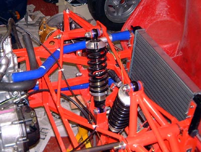
clear that the amount of movement needed couldn't be accommodated by re-drilling the mountings. So, I made some
brackets to move the radiator down about 50mm, and about 18mm to the left. This meant the top-hose fitting cleared
the mounting flange. It also has the secondary effect that the fan switch doesn't bash into the same flange, which
it did before.
I then started trial fitting bits of the cooling system together. However, I didn't get too far as I need the expansion tank and I'm not sure whether to connect that into the top of the bottom hose. I suspect the latter, that's the way the Dax is done, but I'll need to think a bit. What's more, I haven't got an expansion tank yet.
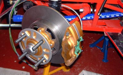 Finally, I had a little fiddle with the issue I've got with the front brakes
which means that I couldn't get the pads into one of calipers. After I found some spacer washers of a slightly
better size, and after I got the green backing paint off the pads, I could get both sides together. It's not ideal
as there's fair bit of binding at the moment. However, I hope that this will go away as the bakes bed in, and the
pads start to wear. If not, I'll have to find some way of removing a bit of the braking material. However, at least
I can now bleed the brakes.