 Having thought about the expansion tank fitting overnight, and asked all the
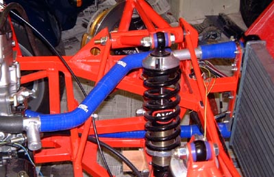
cam7 bods, I put the top hose together, as in this photo. Yes, you're right and the pipe does go through the front
suspension. However, I reckon (he said over confidently) that there's no way the rocker will ever touch it.
Having thought about the expansion tank fitting overnight, and asked all the
cam7 bods, I put the top hose together, as in this photo. Yes, you're right and the pipe does go through the front
suspension. However, I reckon (he said over confidently) that there's no way the rocker will ever touch it.
There's no hose clips on this yet, because I haven't got enough. What's more I will have to take the temperature sender tee out again, anyway, as I have to tap it to 3/8" BSP which can only be done when the tap actually arrives!
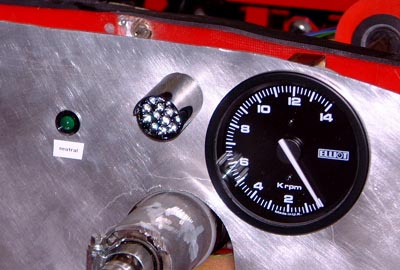
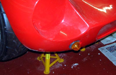 So, it was back to the electrics again. However, now it was actually fitting
the lights. First up are the front ones and in particular the indicators. I only had time to put this one in but
it does already work. That is, the car now glows in the dark, which must be a step forward.
So, it was back to the electrics again. However, now it was actually fitting
the lights. First up are the front ones and in particular the indicators. I only had time to put this one in but
it does already work. That is, the car now glows in the dark, which must be a step forward.
I had some good news today in that I sold my Dax. (Going to be sorry to see it go, though.) If nothing else, this will give me some extra room in the garage and will possibly help me store a trailer at some point.
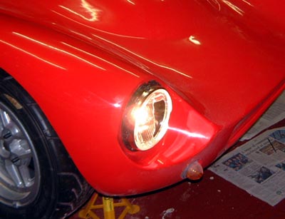 I finished fitting the front lamps this evening, although I did spend some of the day hunting
down some other required bits. In particular, I've now got an expansion tank so I can finish the cooling system.
I finished fitting the front lamps this evening, although I did spend some of the day hunting
down some other required bits. In particular, I've now got an expansion tank so I can finish the cooling system.
Of course, muppet that I am, I managed to drop one of the headlamps on the floor and broke the lens. So, I'll have to buy another one! Dooohhh. Luckily, they were the cheapest headlamps that I could find.
I suppose I could try telling the scrutineers that it's a weight saving technique? Or perhaps some way of avoiding having to put tape on the lenses?
I phoned Stafford Vehicle Components today and ordered a new headlamp. :-( In the relatively short time that I had in the garage today I put a few hose clips on the top hose so as to make it, I hope, water tight. At the moment the connections to the temperature sender tee are still loose as I haven't yet got the 3/8" BSP tap I need to connect the water temperature sender.
I've actually started to entertain the notion that I might be able to have a go at starting the engine this weekend. If I can get the cooling piped up and some sort of exhaust lashed up then I might be able to try it. Hence, I'm not worrying about the water temperature sender as I can just leave it out for now.
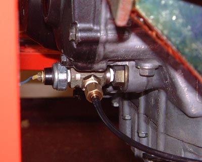 What is important is an oil pressure display so I used some adapters that I'd
ordered from Think Automotive to connect both the pressure light and the pressure gauge capillary to the takeoff
on the front of the engine. You can see here the pressure switch (on the left) and the capillary for the pressure
gauge (at the bottom/front). You can see various bits of PTFE tape in the photo. Hopefully these will stop any
of the leaks that you sometimes get with this sort of arrangement.
What is important is an oil pressure display so I used some adapters that I'd
ordered from Think Automotive to connect both the pressure light and the pressure gauge capillary to the takeoff
on the front of the engine. You can see here the pressure switch (on the left) and the capillary for the pressure
gauge (at the bottom/front). You can see various bits of PTFE tape in the photo. Hopefully these will stop any
of the leaks that you sometimes get with this sort of arrangement.
In fact, I haven't actually got the oil pressure warning light yet. I have ordered a 26 mm diameter LED cluster for this and it was out of stock at the suppliers. However, I had an email this evening that said it had now been despatched.
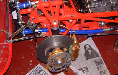
I took off the left hand sidepod. This is needed for several reasons in that I need to get access to connect up the bottom hose and I need to think about the exhaust which exits through this sidepod. Luckily the rivnuts I used for attaching this sidepod make doing this very easy.
One reason for doing this was to see if the exhaust had a chance of fitting. In fact, it looks as though it's going to fit fairly well which, after the hernia inducing process of getting the Dax exhausts to fit, is very welcome. I can't work out exactly where it will be though, as I need the nuts and gaskets that I've ordered to get the fitting just right.
 I'm really beginning to think that as long as I get the exhaust bits and pieces
from Honda then starting the engine this weekend is a real possibility. So, I really wanted to get on with the
cooling system.
I'm really beginning to think that as long as I get the exhaust bits and pieces
from Honda then starting the engine this weekend is a real possibility. So, I really wanted to get on with the
cooling system.
I had a look at fitting the old fan that I have today but I'm not sure really whether it isn't too big. SVC seem to sell some fairly cheap ones so I might just order another one. SVC did in fact deliver a replacement headlamp today and that was easily fitted so the car looks OK again.
Something else that came today was the rest of an order that I placed with Maplin ages ago. In particular, there was the LED cluster that I ordered to make a low oil pressure warning light. So, I fitted that to the dash and tested it. It's certainly very bright and should be even brighter with the engine moving and the alternator output pushing the battery voltage higher.
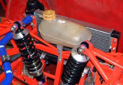 A few days ago I raided a scrappy and found an old expansion tank from a Sierra;
the same sort, in fact, as I used for the Dax. I spent ages trying to find the right way to mount this and finally
ended up with it in the position shown here. It's supported by a couple of aluminium strips which are secured to
the chassis with a couple of rivnuts.
A few days ago I raided a scrappy and found an old expansion tank from a Sierra;
the same sort, in fact, as I used for the Dax. I spent ages trying to find the right way to mount this and finally
ended up with it in the position shown here. It's supported by a couple of aluminium strips which are secured to
the chassis with a couple of rivnuts.
It seems to fit here quite neatly. Best of all, the original hose from the bottom of the tank seems to fit nearly well down to the bottom hose. Unfortunately it's not nice blue silicone but as long as water doesn't get out who cares!
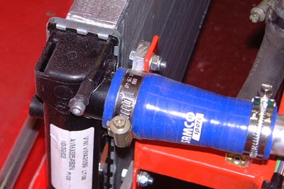 Finally, I did something that I did to the Westfield many years ago and sealed
up the unrequired hole at the top of the radiator by tapping the radiator to M5 and fitting a bolt sealed with
some silicone sealant.
Finally, I did something that I did to the Westfield many years ago and sealed
up the unrequired hole at the top of the radiator by tapping the radiator to M5 and fitting a bolt sealed with
some silicone sealant.
Hopefully, water won't pour out of it all the way it did when I filled the Westfield many years ago.
Tomorrow I should get the cooling system piped up, and possibly filled too. I'll also see about getting the bits from Honda.
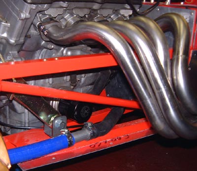
 Another day, and it was on with the plumbing. With the sidepod off it was easy to get at
where the bottom hose would run. With the addition of a couple of bits of aluminium tubing and a tee to connect
to the bottom of the header tank the hose looked like this photo. I will have to relieve the vertical "front"
of the sidepod slightly to clear the hose but that's no big deal. I'm also going to have to cut a socking great
hole in the top for the headers to go through.
Another day, and it was on with the plumbing. With the sidepod off it was easy to get at
where the bottom hose would run. With the addition of a couple of bits of aluminium tubing and a tee to connect
to the bottom of the header tank the hose looked like this photo. I will have to relieve the vertical "front"
of the sidepod slightly to clear the hose but that's no big deal. I'm also going to have to cut a socking great
hole in the top for the headers to go through.
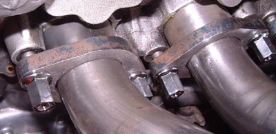 The exhaust headers are held on by snazzy nuts that I ordered from Mr Honda
a few days ago. They're a really odd size: M7x1 and hence you need the real thing. Luckily the aforesaid Japanese
gentleman phoned up to tell me that they were in. So, I went over to Hallens in Cambridge to pick up the nuts,
some copper sealing rings for the exhaust headers and some sump gaskets. Fitting the exhaust headers was fairly
easy except that the copper rings just fall out. I held them in with a few blobs of grease while I was fiddling
around with nuts and trying to hold things with two hands while using another two to manipulate the spanners. The
photo here shows what these nuts look like, with everything all in place.
The exhaust headers are held on by snazzy nuts that I ordered from Mr Honda
a few days ago. They're a really odd size: M7x1 and hence you need the real thing. Luckily the aforesaid Japanese
gentleman phoned up to tell me that they were in. So, I went over to Hallens in Cambridge to pick up the nuts,
some copper sealing rings for the exhaust headers and some sump gaskets. Fitting the exhaust headers was fairly
easy except that the copper rings just fall out. I held them in with a few blobs of grease while I was fiddling
around with nuts and trying to hold things with two hands while using another two to manipulate the spanners. The
photo here shows what these nuts look like, with everything all in place.
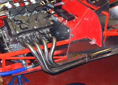 Which left the side of the car looking like this. The obvious thing missing
is some form of silencer without which starting the engine is going to cause our neighbours a bit of angst.
Which left the side of the car looking like this. The obvious thing missing
is some form of silencer without which starting the engine is going to cause our neighbours a bit of angst.
There's a standard Fireblade can on its way to me but in the absence of that I borrowed the exhaust for a Phoenix from Craig, yet another cam7er.
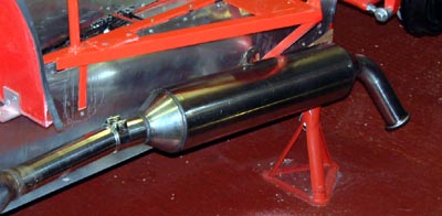 To be honest, this doesn't really fit because the side impact protection is in the way but I managed
to get it nearly jammed into place. There's kind of a big hole just before the can but I'll just put up with that
for now. Hopefully, this will just allow me to run the engine without offending too many people.
To be honest, this doesn't really fit because the side impact protection is in the way but I managed
to get it nearly jammed into place. There's kind of a big hole just before the can but I'll just put up with that
for now. Hopefully, this will just allow me to run the engine without offending too many people.
Next, I filled up the cooling system, just using water for now as I'm bound to want to drain it at some point and wasting all that expensive coolant is silly.
 I sealed up the cam chain tensioner using some liquid gasket rather than buying a real one. The next
thing to do was to change the oil filter, which was easy. I had bought a new one from Mr Honda as well as the various
nuts and things. He's not the cheapest place in the world for filters though...
I sealed up the cam chain tensioner using some liquid gasket rather than buying a real one. The next
thing to do was to change the oil filter, which was easy. I had bought a new one from Mr Honda as well as the various
nuts and things. He's not the cheapest place in the world for filters though...
Then I started pouring some oil in and looking through the little window on the front of the clutch housing which is where you look at the level on this engine. The chap I bought the engine off had sad that it was empty of oil but it became obvious after a while that the reason the little window had changed colour wasn't just oil running past it but because it was submerged totally. By the time I realised this I must have massively overfilled the engine to the sort of position where I couldn't possibly start it. Obviously, the engine could not have been empty of oil after all. Although, it all looked very clean.
So, there was nothing for it than to completely drain it out again. As I don't really know what it was mixing with and I don't want to run the risk of introducing some garbage in with recycled oil then I'll just have to throw away the stuff I bought a couple of days ago.
Finally, I started planning the sort of bracket I need for the clutch release lever. Hopefully, tomorrow I'll go and get some more oil, fill the engine with it, add the fuses I need to enable the ignition units and start the engine!
I'll believe it when I see (and hear) it!
A momentous day this! First of all we went out to Halfords and bought some bike engine oil to replace the stuff I contaminated in yesterday's muppet-tastic moment. I shall have to drain this new oil again, but I shall drain it directly back into the bottle it came out of and I'll be happy to use it again.
Once that oil was in (and I had washed three cars and faffed around for a while) I could no longer put off the evil moment.
First of all I disconnected the low tension side of the coils and, with the right fuse put in the fusebox, pressed the starter button. The engine churned around and the oil pressure light flickered and the oil pressure gauge moved a bit. Presumably that means that there is going to be oil pressure once it get going.
So, I re-connected the coils, put a tie wrap around the choke lever to put it full on, and tried again. This time it coughed and spluttered. Then it fired and stopped. Then it fired and ran! I released the choke pretty quickly as it was hunting badly and things smoothed out a bit. (I wonder if a choke cable will really be necessary?)
It made a fabulous noise for a while until there was an ominous clank and Craig's silencer gave up the attempt at hanging on. But it still runs! Not surprisingly, it sounds just like a sports bike, apart from the noise coming from the complete absence of a silencer of course! This link should allow you to see a video of the engine being started and twiddled with slightly. Unfortunately, I forgot to turn the radio off!
After that it was back to more mundane issues. With the engine running it seems sensible to get the transmission sorted. The big missing bit here is the support for the centre bearing on the propshaft. I've been thinking about this for a while. The prop has two sections and there are three UJs. The problem is that a UJ is not a constant-velocity joint and the normal approach on a single section propshaft is to align the joint yokes 90° out of phase. This has the effect of making the output shaft motion constant, assuming the input and output shafts are parallel. The prop itself, though, is still accelerating and decelerating.
With a two section prop this simple trick doesn't work. In fact, the joints on the rear section are in-phase with each other. Some thought makes me think that therefore the rear prop section should be positioned so the UJ at the end is exactly in line. (That is, you wouldn't really need it.) As long as that section is parallel to the input then the pair of (out of phase) UJs on the front section should give the required constant velocity.
 Hence, I spent a while working out what sort
of support I would need that would ensure that the rear prop section was pretty much in line with the input to
the diff. This is all made rather more difficult by the race chassis in the the diff is much higher, relatively,
than would normally be the case. This has the effect of requiring the bearing support to be taller too.
Hence, I spent a while working out what sort
of support I would need that would ensure that the rear prop section was pretty much in line with the input to
the diff. This is all made rather more difficult by the race chassis in the the diff is much higher, relatively,
than would normally be the case. This has the effect of requiring the bearing support to be taller too.
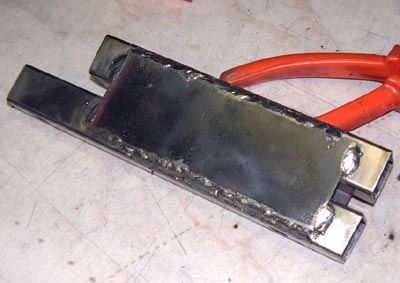
So, I finally fabricated this magnificent lump of welded steel made from some 25mm square tube and some plate. There are some M10 nuts welded inside so as to make it easier to fit it. (Actually, it would probably be impossible.) The support is asymmetric because the requirement to keep the rear prop section in line with the diff nose means that the prop has to run down the right hand side of the tunnel
 So, after
a lot of time fabricating this I bolted it into place and finally had a propshaft that stayed in one place.
So, after
a lot of time fabricating this I bolted it into place and finally had a propshaft that stayed in one place.
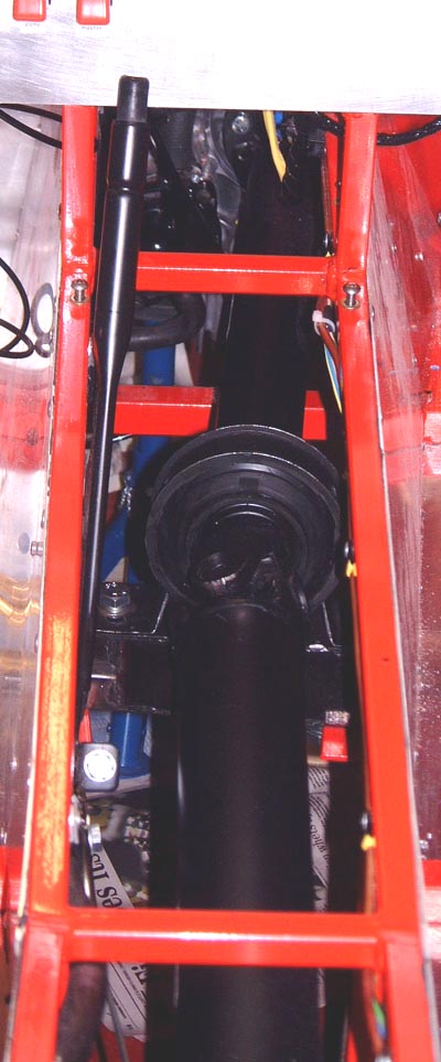
You can just about see in this photo that the rear section of the prop is in a line with the side of the tunnel. (It's horizontal, too.)
Some sort of foreshortening effect seems to make the front section look like a much sharper angle than is actually the case.
With the prop now in place I can look to fitting the reverse drive. This is, like the bearing support, going to need some more thought!
 With the centre bearing support done, I could look to the reverse unit which I think is
the one bit of "engineering" work that needs doing. As I mentioned a while ago I thought the unit was
going to have to be mounted on top of the propshaft. I saw another half built car at today's open day at the Kit
Car Workshop and that one has the unit above the shaft too. So, I set to making brackets and so on to support the
unit in place. The positioning of it turns out to be really tricky but I think it's OK now. I've mounted it on
some pieces of M8 studding so I can move it up and down slightly should there be a problem. I can only really find
out by trying though.
With the centre bearing support done, I could look to the reverse unit which I think is
the one bit of "engineering" work that needs doing. As I mentioned a while ago I thought the unit was
going to have to be mounted on top of the propshaft. I saw another half built car at today's open day at the Kit
Car Workshop and that one has the unit above the shaft too. So, I set to making brackets and so on to support the
unit in place. The positioning of it turns out to be really tricky but I think it's OK now. I've mounted it on
some pieces of M8 studding so I can move it up and down slightly should there be a problem. I can only really find
out by trying though.
One issue is that the unit sticks very slightly above the tunnel top. I'll have to make some sort of power bulge in the top, but I don't think that's too much of an issue. It was worth it to get the unit level. There was a lug on the top of the motor which I ground off to reduce the worst of the bulginess.
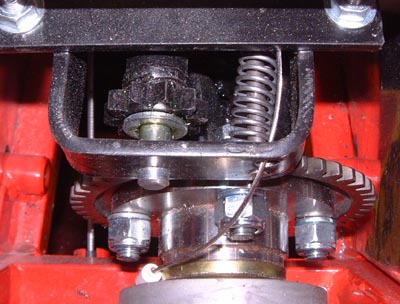 This is the workings of the reverse unit. You can see the pinion that engages with the
ring gear. It's pulled into engagement by the cable that you can see on the right, resisted by that spring that's
also over there.
This is the workings of the reverse unit. You can see the pinion that engages with the
ring gear. It's pulled into engagement by the cable that you can see on the right, resisted by that spring that's
also over there.
With that done I have to do things like make a lever for actuating the reverse, but that should probably wait until I've got the gearchange in position. I'm hoping that that will largely be a "just fit it" issue. I do, though, have to do the wiring for the reverse unit but that's no big issue. I need to get a switch for it though.